Summary of the utility model
In view of this, this utility model provides a rotary shock-absorbing seat frame platform for automobiles, with a simple structure, which can appropriately reduce manufacturing precision requirements and avoid issues such as abnormal noises, looseness, poor movement, and sticking; Installation and use do not require large height spaces, enhancing seat comfort while providing ample room for ventilation and heating components.
The skeleton platform of the automotive rotating shock-absorbing seat of this utility model includes a base, an upper support frame, and a linkage mechanism hinged together. The linkage mechanism can be driven to deform vertically between the base and the upper support frame, and the linkage mechanism is subjected to an upward-deforming elastic preload.
Furthermore, it further includes a damper, which is arranged between the base and the upper support frame to form vertical damping.
Furthermore, the linkage mechanism includes a linkage assembly I and a linkage assembly II. The linkage assembly I includes a connecting rod I and a transition connecting rod I hinged to the connecting rod I that can swing in the vertical direction. The connecting rod assembly II includes a connecting rod II and a transition connecting rod II hinged that can swing up and down with the connecting rod II. The X-shaped cross hinge between the connecting rod I and the connecting rod II can swing up and down. One end and the other end of the connecting rod I are hinged to the base and the upper support frame via the transition rod I that can swing up and down, respectively. One end and the other end of the connecting rod II can be hinged to the base and the upper support frame by swinging vertically via the transition connecting rod II;
The elastic preload is adjustable.
Furthermore, the connecting rod assembly I and connecting rod assembly II are arranged in two sets and arranged side by side.
Furthermore, the elastic preload is applied to any hinge position of the linkage mechanism, forming an upward swinging trend at this hinge position.
Furthermore, the upper end of connecting rod I is hinged to the upper support frame, and the lower end is hinged to the base via transition connecting rod I, forming an upward angle with the transition rod I; The upper end of connecting rod II is hinged to the upper support frame via transition rod II, and the lower end is hinged to the base, forming an upward angle between the transition connecting rod II and the connecting rod II.
Furthermore, the linkage mechanism further includes a hollow shaft I and a hollow shaft II. The connecting rod I or transition linkage I is hinged to the base or upper support frame via hollow shaft I, and the connecting rod II or transition connecting rod II is hinged to the base or upper support frame via hollow shaft II; The elastic preload force is applied by torsion spring I and torsion spring II. The torsion spring I passes through hollow shaft I, with one end pressed against the set position of hollow shaft I and the other end at a relatively fixed position; The torsion spring II is installed inside the hollow shaft II, with one end pressed against the set position of the hollow shaft II and the other end at a relatively fixed position corresponding to it;
The elastic force of Torsion Spring I and/or Torsion Spring II is adjustable, allowing the elastic preload to be adjustable.
Furthermore, both the base and the upper support frame have a frame-type structure; The hollow shaft I is rotatably fitted to support the rear position of the upper support frame, the upper end of the connecting rod I is fixed to the hollow shaft I, and the transition connecting rod I is hinged to the side of the base corresponding to the base; The hollow shaft II is rotatably fitted to support the front position of the upper support frame, the transition connecting rod II is fixed to the hollow shaft II, and the lower end of the connecting rod II is hinged to the side of the base corresponding to the base; The damper is installed between the front of the base and the front of the upper support frame, forming a damper between the base and the upper support frame.
Furthermore, the rear of the upper support frame is provided with rear support lugs for rotatably supporting the hollow shaft I. The torsion spring I passes through hollow shaft I, with one load-bearing end pressing against the limiting groove formed on the wall of hollow shaft I, and another load-bearing end extending out from hollow shaft I and pressing against the rear support ear;
The linkage mechanism further includes a spring force adjustment mechanism arranged on the upper support frame. The hollow shaft II is rotatably fitted to support between the two sides of the upper support frame. The torsion spring II passes through the hollow shaft II, with one load-bearing end pressed against the limiting groove formed on the wall of the hollow shaft II, and the other load-bearing end extending out from the hollow shaft II to the adjustment end of the spring force adjustment mechanism.
Furthermore, a hinge shaft is fixedly connected between the ends of the two sets of linkage assembly II and hinged to both sides of the base via the hinge shaft.
Beneficial effects of this utility model: The automotive rotary shock-absorbing seat frame platform of this utility model adopts a linkage mechanism that is hinged and can be driven to deform up and down, converting the sliding motion of the shock absorber in the prior art into rotational motion, which can appropriately reduce manufacturing precision requirements and avoid issues such as abnormal noise, looseness, poor movement, and sticking; The rotating connecting rod mechanism does not require large height space, thus offering a large stroke that greatly enhances seat comfort, while also providing enough space to arrange ventilation and heating components; The entire structure of this utility model integrates shock absorption and frame into one, featuring a simple structure, easy installation, and cost savings.
Specific embodiments
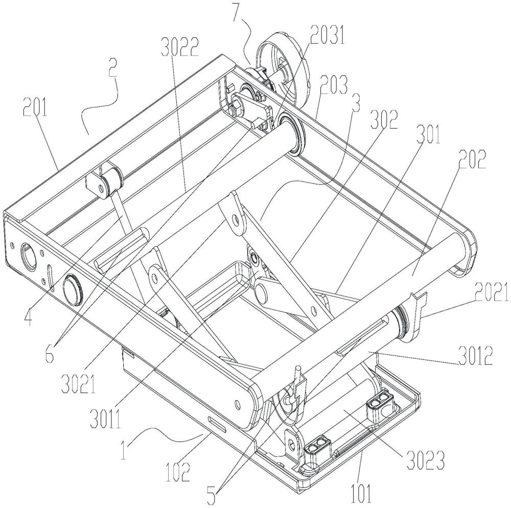
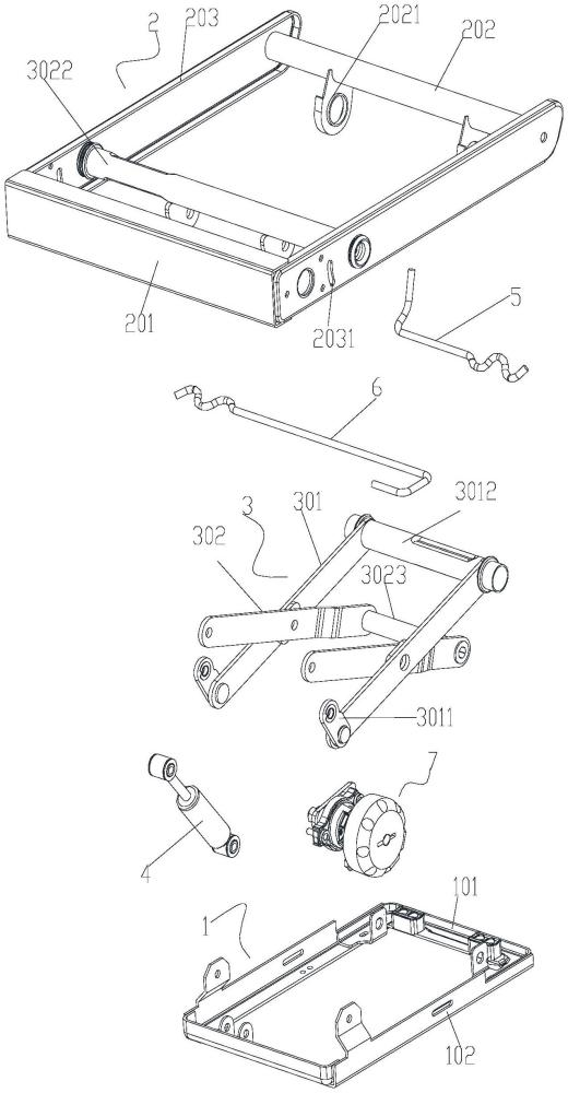
As shown in Figures 1-2: The automotive rotary shock-absorbing seat frame platform in this embodiment includes a base 1, an upper support frame 2, and a linkage mechanism 3 hinged together. The linkage mechanism 3 can be driven to deform vertically and hinged between the base 1 and the upper support frame 2, and an upward-deforming elastic preload is applied;
A connecting rod mechanism refers to a component composed of several connecting rods hinged to each other, generally using an X-shaped hinge to achieve vertical deformation, which will not be elaborated here; Of course, hinges in other directions can also be used between connecting rods, such as direct inclined hinges and applying a set elastic preload, which can also form vertical deformation structures, which will not be elaborated here; Since all fitting pairs of this structure use articulated connections, the sliding pair from the prior art has been removed, thereby solving the technical problems of the sliding pair.
In this embodiment, a damper 4 is also included, which is arranged between the base 1 and the upper support frame 2 to form a vertical damping motion. The damper 4 belongs to a mechanical structure in the prior art capable of damping effects, such as a piston-type damper, which will not be repeated here.
In this embodiment, the elastic preload is adjustable. Generally, the elastic preload refers to the force applied by elastic elements, which can achieve reciprocating elastic compression and release, thereby enabling the linkage mechanism 3 to deform vertically and reciprocately to achieve shock absorption, and serves the general function of a shock absorber; It can be springs, spring clips, etc., which will not be repeated here.
In this embodiment, the linkage mechanism 3 includes a linkage assembly I and a linkage assembly II. The linkage assembly I includes a connecting rod I.301 and a transition linkage I.3011 hinged to the connecting rod I.301 that can swing in the vertical direction. The linkage assembly II includes a linkage II III302 and a transition rod II 3021 that can swing vertically with the linkage II. The X-shaped cross-hinged connecting rod I.301 and the connecting rod II.302 can swing vertically. One end and the other end of connecting rod I301 can be hinged to the base 1 and the upper support frame 2 by swinging vertically via the transition connecting rod I3011. One end and the other end of the connecting rod II.302 can be hinged to the base 1 and the upper support frame 2 by swinging vertically via the transition connecting rod II.3021; As shown in the figure, one end of connecting rod I.301 can be directly hinged to the base, and the other end is hinged to the upper support frame 2 via the transition connecting rod I.3011, and vice versa; Of course, one end of the connecting rod II.302 can be directly hinged to the base, and the other end is hinged onto the support frame 2 via the transition connecting rod II.3021, and vice versa, which will not be repeated here; In this structure, the transition rods I.3011 and II.3021 are hinged to the base 1 and the upper support frame 2 through transition linkages I.3011 and II.302, so that the linkage mechanism 3 does not deform transversely during vertical deformation, and the structure is relatively simple; X-shaped hinge refers to crossing and hinging connecting rod I301 and connecting rod II.302; The hinge mentioned in this utility model refers to oscillation in the vertical direction, with the expectation of single degrees of freedom swing, which will not be repeated here.
In this embodiment, the linkage assembly I and the connecting rod assembly II are arranged in two sets and arranged side by side; As shown in the figure, in this structure, connecting rod I.301 and transition linkage I.3011, as well as connecting rod II.302 and transition connecting rod II.3021, are all arranged in two parallel transverse lines, providing relatively stable deformation and support, which will not be repeated here.
In this embodiment, the elastic preload is applied to any hinge position of the linkage mechanism 3, forming an upward swinging trend at this hinge position; The hinge position refers to the position where all hinges are connected between the linkage mechanism 3 and the base 1, the upper support frame 2, and the linkage mechanism 3; Elastic preload can be applied at any or more hinge positions and to create an upward swing tendency for the linkage mechanism, both of which achieve the purpose of the utility model.
In this embodiment, the upper end of the connecting rod I.301 is hinged to the upper support frame 2, which requires the corresponding hinge position and is a typical mechanical adaptation structure that will not be repeated here; The lower end of connecting rod I.301 is hinged to base 1 via transition connecting rod I.3011. Similarly, base 1 requires corresponding hinge positions, which is a typical mechanical adaptation structure and will not be repeated here; Moreover, the transition connecting rod I3011 forms an upward angle with the connecting rod I.301, ensuring ample swinging space between the transition connecting rod I.3011 and the connecting rod I.301 without occupying upper space, allowing it to be used to arrange other functional components; Similarly, the upper end of the connecting rod II.302 is hinged to the upper support frame 2 via the transition connecting rod II.3021. The upper support frame 2 requires the corresponding hinge position, which is a typical mechanical adaptation structure and will not be repeated here; The lower end of the connecting rod II.302 is hinged to base 1. Similarly, base 1 requires the corresponding hinge position, which is a typical mechanical adaptation structure and will not be elaborated here; Moreover, the transition linkage II.3021 forms an upward angle with the connecting rod II.302, which of course has the same effect as the connecting rod I.301 and transition linkage I, so it will not be repeated here.
In this embodiment, the linkage mechanism 3 further includes a hollow shaft I.3012 and a hollow shaft II.3022. The linkage I.301 or transition linkage I.3011 is hinged to the base 1 or the upper support frame 2 via the hollow shaft 3012, and the connecting rod II.3022 or the transition linkage II.3022 is hinged to the base 1 or the upper support frame 2 via the hollow shaft II.3022. Any of the above hinged connection structures can be chosen, and the purpose of the utility model can be achieved. The elastic preload is applied by torsion spring I5 and torsion spring II.6. The torsion spring I.5 is inserted through hollow shaft I.3012, with one end pressed against the set position of hollow shaft I.3012 and the other end at a relatively fixed position. Hinge refers to the rotational fit between the hollow shaft (including hollow shaft I.3012 and hollow shaft II.3022) and the base or upper support frame, thereby enabling the connecting rod I.301, the transition connecting rod I.3011, and the connecting rod II.302, The transition connecting rod II.3022 can form a hinge between the base and the upper support frame; By forming a hinge through hollow shafts (including hollow shaft I.3012 and hollow shaft II.3022), the strength of the hinge connection can be improved, ensuring structural durability, while also providing space for the torsion springs (including torsion springs I.5 and II.6), ensuring there is sufficient functional space to accommodate other components, such as heating and ventilation parts, which will not be repeated here;
The setting part refers to the corresponding part designed in hollow shaft I.3012 that can support one end of the torsion spring I.5, such as by grooving or protruding parts. This is a general mechanical structure setting and will not be repeated here. At the same time, the corresponding relatively fixed position refers to the position corresponding to the other end of the torsion spring I.5 and does not participate in rotation, such as the corresponding position on the base or upper support frame, such as a slot or protrusion, used to press against the other end of the torsion spring I.5, which is a general mechanical structure design. I won't repeat them here; The torsion spring II.6 is inserted inside the hollow shaft II.3022, with one end pressed against the set position of the hollow shaft II.3022 and the other end at a corresponding relatively fixed position. This structure is based on the same principle as the hollow shaft I.3012 and will not be repeated here;
The elastic force of torsion spring I.5 and/or torsion spring II 6 is adjustable, making the elastic preload adjustable; There are various ways to adjust the elastic force. For example, torsion spring I.5 and torsion spring II.6 can be either selectively used or each is pressed against one end by a pressing block. The pressing block can be connected by threads to a deformation fixed position relative to the linkage mechanism, such as the base or upper support frame, which can achieve adjustable and lockable positions. Alternatively, rotating the pressing block can change position and lock it using conventional mechanical structures. All are typical mechanical structural applications and will not be elaborated here.
In this embodiment, both the base 1 and the upper support frame 2 are frame-type structures. A frame-type structure refers to a frame structure composed of two side edges, a front edge, and a rear edge, usually rectangular or nearly rectangular, and will not be repeated here; The hollow shaft I.3012 rotatably fits and supports the rear position of the upper support frame 2, which can be hinged at the rear or at the corresponding positions on both side edges, and will not be repeated here; The upper end of connecting rod I.301 is fixed to the hollow shaft I.3012, and the transition linkage I.3011 is hinged to the side 102 corresponding to the base 1. As shown in the figure, the two side edges 102 of the base 1 are respectively provided with hinge lugs, and the two transition connecting rods I.3011 are respectively hinged to the two side ends 102. The structure is simple, compact, and easy to install; The position of the hollow shaft II.3022 rotatably fitted to the front of the upper support frame 2 may be hinged to the front or to the corresponding positions on both side edges, which will not be repeated here; The transition connecting rod II.3021 is fixed to the hollow shaft II.3022 and can be fixed by existing mechanical fixing methods such as welding. The lower end of the connecting rod II.302 is hinged to the side of the base 1, as shown in the figure. The two side edges 102 of the base 1 are each equipped with hinge lugs, and the two connecting rods II.302 are hinged to the two side ends 102, which belong to a typical mechanical hinge structure and will not be elaborated here; The damper 4 is installed between the front edge of base 1 and the front edge of the upper support frame 2, forming a damper between the base and the upper support frame. The damper is installed in a front position, giving the utility model considerable application space in the middle and rear sections and adapting to ergonomic requirements. The damper installation generally adopts a structure where the upper end hinges the front of the upper support frame 2 and the lower end hinges the front of base 1, requiring hinge lugs and other structures, which will not be repeated here.
In this embodiment, the rear 201 of the upper support frame 2 is provided with a rear support lug 2021 for rotatably supporting the hollow shaft I. The torsion spring I5 passes into the hollow shaft I3012, with one load-bearing end pressing against the limiting groove formed on the wall of hollow shaft I3012, and another load-bearing end extending out from hollow shaft I3012 and pressing against the rear support ear; As shown in the figure, a strip-shaped groove is formed along the axis on hollow shaft I.3012, i.e., a limiting groove. One load-bearing end of torsion spring I.5 is bent into a limiting section, and after passing through hollow shaft I.3012, it is elastically fitted into the limiting groove, thereby forming a limiting position in the circumferential direction. As shown in the figure, a flange is formed on the rear support ear 2021, which presses against the other load-bearing end of torsion spring I.5, thereby applying rotational preload on hollow shaft I.3012. This rotational preload causes the hollow shaft I.3012 to drive the connecting rod 301 to swing upward, thereby forming a shock-absorbing structure;
The linkage mechanism 3 further includes a spring force adjustment mechanism 7 arranged on the upper support frame 2. The hollow shaft II.3022 rotatably fits and supports between the two sides 203 of the upper support frame 2. The torsion spring II.6 passes into the hollow shaft II.3022, with a load-bearing end pressed against a limiting groove formed on the wall of the hollow shaft II.3022. This structure is similar to the structure of the torsion spring I.5 installed on the hollow shaft I.3012 and will not be elaborated here; The other bearing end of torsion spring II.6 extends out from the hollow shaft II, which abuts the adjustment end of the spring force adjustment mechanism; The structure of the spring force adjustment mechanism 7 adopts an existing mechanical structure, with the adjustment end serving as the aforementioned pressing block; As shown in the figure, the spring force adjustment mechanism 7 is installed on the corresponding side 203 of the upper support frame 2, including a knob 701 (generally manual, but can also be electric), a transmission mechanism 702, and an adjustment end 703. The adjustment end is generally a strip-shaped block. The transmission mechanism 702 has a rotating output shaft, which is installed on the power output shaft and can be driven to swing along the shaft's axis. During the swing, it presses against the other bearing end of torsion spring II.6, changing its position to achieve the purpose of adjusting elastic force. The final adjustment to the shock absorption effect will not be repeated here; The transmission mechanism 702 generally adopts a mechanical structure that is driven to rotate and has self-locking capability, such as a ratchet pawl structure, but it must be paired with a reverse release mechanism (such as a pin that can be inserted at different positions) and a worm gear structure with a self-locking angle, meaning it is transmitted to the adjustment end via a knob and can swing. This can be achieved through conventional mechanical structures and will not be repeated here; As shown in the figure, the adjustment end is located on the inner side of the corresponding side 203 of the upper support frame 2. The other load-bearing end of torsion spring II.6 passes through the hollow shaft II.3022, then curves backward, passes through the arc-shaped slot 2031 provided on the corresponding side 203, and then presses against the adjustment end 703. The overall structure is simple and compact, with the adjustment end located on the inner side of side 203 to avoid interference and ensure adjustment accuracy.
In this embodiment, a hinge shaft 3023 is fixedly connected between the ends of the two sets of linkage assemblies II, and is hinged and supported between the two side edges 103 of the base 1 via the hinge shaft 3023. The two side edges 103 are equipped with hinge lugs, which is a typical hinged connection structure with high overall strength, which will not be repeated here.
Structurally, the rear 201 of the upper support frame 2 is an axial structure, and the rear support lugs for supporting and hinging hollow shaft I.3012 are fixed to the rear 201 of the shaft-shaped structure and extend downward, ensuring overall support strength; At the same time, the cross-sections of the front 202 and side 203 are groove-shaped structures, similar to channel steel structures, used to support the damper and other hinged structures to ensure overall strength, so they will not be elaborated here;
The hinged connection points on base 1 to the articulated shaft 3023 and transition connecting rod 3011 are integrally formed (sheet metal) to form hinge lugs, thereby ensuring the load-bearing capacity of the hinge positions and guaranteeing the stability of the entire framework.
Finally, it should be noted that the above embodiments are only intended to illustrate the technical solutions of the present utility model and not to limit them. Although the utility model has been described in detail with reference to preferred embodiments, those skilled in the art should understand that modifications or equivalent substitutions of the technical solutions of this utility model can be made without departing from the purpose and scope of the technical solutions of this utility model, and all such actions should be included within the scope of the claims of the present utility model.










 400-4929-0909
 contact@catarc.com.cn