Clamping device and method for high-frequency heat treatment processTechnical Field
The invention relates to the technical field of heat treatment, in particular to a clamping device and a method for a high-frequency heat treatment process.
Background
With the aim of light weight of automobile manufacturers becoming higher and higher, light-weight and high-strength parts become the trend of development of the automobile industry. The high-frequency heat treatment process is a quenching mode of heating a part to about 900 ℃ by using a high-frequency induction coil and then cooling the part by using quenching liquid, so that the requirements of eliminating stress concentration generated in the forming process, improving the integral strength of the part and improving the fatigue resistance of the part are met. At present, most of high-frequency heat treatment is carried out by positioning one end of the part or directly placing the part on a tool made of high-temperature resistant materials such as ceramics, and the part is easy to deform under complex comprehensive actions such as rapid temperature rise and cooling, residual stress of the part and the like in the heat treatment process. Taking an automobile torsion beam as an example, the deformation mode of the ordinary heat-treated torsion beam mainly comprises an arch shape in the length direction of 6-8mm, a torsion in the length direction of 3-4 degrees, and the deformation is difficult to control; after the two ends of the part are fixed, the induction coil cannot pass through the end part of the part, the integral quenching cannot be finished, and the two ends of the part have partial non-heat-treated areas; and parts can not be accurately positioned, and automation can not be realized.
The patent application with publication number CN104651582A discloses a fixture for integrally quenching a high-strength tubular beam, which prevents bending and deformation from occurring in the quenching process by supporting a plurality of positions at both ends and in the middle of the beam, but the fixture clamps the beam after heat treatment is completed and puts the beam into water for quenching, and the beam still cannot be fixed during heat treatment, so that the problem that an induction coil cannot pass through the end of a part in the heating process cannot be solved.
Disclosure of Invention
The invention aims to provide a clamping device which can clamp and fix two ends of a part and allow an induction coil to pass through the end part of the part for heat treatment.
The invention solves the technical problems through the following technical scheme: the utility model provides a clamping device for high frequency heat treatment process, includes along the lower locating component and the last locating component of vertical direction setting, the lower extreme of pending part length direction places on lower locating component, go up the upper end that locating component can follow vertical direction adjustment fixed position centre gripping part, induction coil can follow the both ends that vertical direction motion passed the part.
According to the invention, the lower positioning assembly supports the part, and the upper positioning assembly is matched with the upper end of the part to keep the part vertical, so that the part is prevented from bearing too large pressure and arching deformation, and the part is not acted by torsional force or pressure in the circumferential direction, so that the torsional deformation of the part is reduced; the induction coil can penetrate through the whole part, so that the whole part is integrally quenched, and the whole part can be subjected to heat treatment.
Preferably, the lower positioning assembly comprises a base, a lower positioning block which is in adaptive fit with the lower end face of the part is connected to the base through a supporting rod, and the induction coil can penetrate through the lower positioning block.
Preferably, the lower end of the supporting rod is inserted into the upper surface of the base and fixed by bolts which are arranged in a sedimentation mode relative to the lower surface of the base, the upper end of the supporting rod is inserted into the lower surface of the lower positioning block and fixed by bolts which are arranged in a sedimentation mode relative to the upper surface of the lower positioning block, and the base and the lower positioning block are fixedly matched with the supporting rod along the circumferential direction.
Preferably, the axial cross section of the part of the support rod inserted into the base and the lower positioning block is a special-shaped surface.
Preferably, go up locating component and include the cylinder, the output orientation locating component down of cylinder, the output of cylinder is connected with the guide bar, the guide bar be connected with the up end adaptability complex of part on the locating piece, induction coil can pass on the locating piece.
Preferably, a fixing plate is fixedly arranged between the upper positioning block and the cylinder, and the guide rod is in sliding fit with the fixing rod along the axial direction and is in fixed fit with the fixing rod along the circumferential direction.
Preferably, the end of the guide rod is inserted into an upper positioning block, and the upper positioning block is fixedly matched with the guide rod along the circumferential direction.
Preferably, the part is a hollow pipe fitting or the two ends of the part are respectively concave, and the lower positioning block and the upper positioning block respectively protrude towards one side of the part and are clamped with the end face of the part.
Preferably, one surface of the lower positioning block and one surface of the upper positioning block facing the part form a guide section, a positioning section and a fixing section respectively, the fixing section is connected with the supporting rod or the guide rod respectively, a transition step is formed between the positioning section and the fixing section, the end surface of the part is abutted against the transition step, the positioning section is in interference fit with the inner side of the end surface of the part, the guide section is connected with one end of the positioning section facing the part and is in inward drawing transition, and the drawing angle is 0.3-1 degrees.
The invention also provides a high-frequency heat treatment method using the clamping device, which comprises the following steps
S1: arranging the clamping device in the heat treatment equipment, opening a protective door of the heat treatment equipment, and grabbing parts through a manipulator to enable the parts to be vertical;
s2: placing the lower end of the part on the lower positioning assembly, keeping the part in a vertical state, enabling the upper positioning assembly to move in the vertical direction to clamp the upper end of the part, withdrawing the mechanical arm from the heat treatment equipment, and closing the protective door;
s3: starting the induction coil, enabling the induction coil to move upwards from the lower positioning assembly to the upper positioning assembly, heating the part to a set temperature, spraying quenching liquid on the part by the nozzle along with the movement of the induction coil, and returning the induction coil to an initial position in the part cooling process;
s4: and after cooling, opening the protective door, grabbing the part through the manipulator, controlling the upper positioning assembly to be separated from the upper end face of the part, taking out the part through the manipulator, and finishing quenching.
The clamping device and the method for the high-frequency heat treatment process have the advantages that: the lower positioning assembly supports the part, and the upper positioning assembly is matched with the upper end of the part to keep the part vertical, so that the part is prevented from bearing too large pressure and arching deformation, and the part is not under the action of torsional force or pressure in the circumferential direction, so that the torsional deformation of the part is reduced; the induction coil can penetrate through the whole part, so that the whole part is integrally quenched, and the whole part and all parts can be subjected to heat treatment. The supporting rod and the guide rod are respectively and fixedly matched with the lower positioning block and the upper positioning block in the circumferential direction, so that the upper positioning block and the lower positioning block are prevented from rotating in the circumferential direction in use, and the torsion amount of parts is reduced; the parts can be accurately matched with the upper positioning block and the lower positioning block, so that the automatic taking and placing of the parts are conveniently realized, the working efficiency and the stability are improved, and the possible risks and abnormalities of manually taking and placing the products are reduced; the tip of piece is earlier finely tuned the position through the direction section, then inserts the location section and fixes, and convenient to use reduces the requirement of placing the position precision to the part.
Drawings
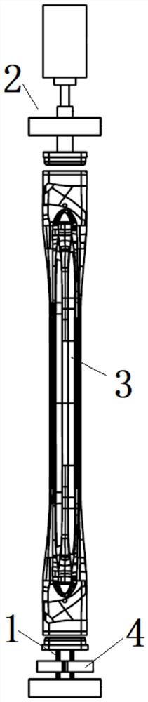
FIG. 1 is a schematic view of a clamping device for a high frequency thermal processing process provided by an embodiment of the present invention;
FIG. 2 is a schematic view of a lower positioning assembly of a clamping device for a high frequency thermal processing according to an embodiment of the present invention;
FIG. 3 is a schematic view of a lower positioning block of the clamping device for the HF heat treatment process according to an embodiment of the present invention;
FIG. 4 is a cross-sectional view of a support bar of a clamping device for a high frequency thermal processing process provided by an embodiment of the present invention;
fig. 5 is a schematic view of an upper positioning assembly of a clamping device for a high-frequency thermal treatment process according to an embodiment of the present invention.
Detailed Description
To make the objects, technical solutions and advantages of the present invention more apparent, the technical solutions of the present invention are described below in detail and completely with reference to the accompanying drawings, and it is apparent that the described embodiments are some, but not all embodiments of the present invention. All other embodiments, which can be derived by a person skilled in the art from the embodiments given herein without making any creative effort, shall fall within the protection scope of the present invention.
As shown in fig. 1, the present embodiment provides a clamping device for a high-frequency heat treatment process, which includes a lower positioning assembly 1 and an upper positioning assembly 2 arranged along a vertical direction, wherein a lower end of a to-be-treated part 3 in a length direction is placed on the lower positioning assembly 1, the upper positioning assembly 2 can adjust a fixed position along the vertical direction to clamp an upper end of the part 3, and an induction coil 4 can move along the vertical direction to pass through two ends of the part 3.
In the embodiment, the lower positioning component 1 supports the part 3, and the upper positioning component 2 is matched with the upper end of the part 3 to keep the part 3 vertical, so that the part 3 cannot bear too large pressure to prevent the part from arching and deforming, and the part 3 is not acted by torsional force or pressure in the circumferential direction, so that the torsional deformation of the part 3 is reduced; the induction coil 4 can penetrate the entire part 3 to quench the entire part 3, ensuring that the entire part 3 can be heat treated.
With reference to fig. 2, the lower positioning assembly 1 includes a base 11, a lower positioning block 13 which is matched with the lower section of the part 3 in a adaptability manner is connected to the base 11 through a support rod 12, the induction coil 4 can penetrate through the lower positioning block 13, so that the induction coil 4 can be arranged between the lower positioning block 13 and the base 11 after being fixed on the base 11, when heat treatment is carried out, the induction coil 4 penetrates through the lower positioning block 13 and then sweeps out the whole part 3, and the base 11 can be fixed on a horizontal plane in a welding mode, a screwing mode and the like, so that the lower positioning block 13 can be matched with the vertically arranged part 3.
The lower extreme of bracing piece 12 inserts base 11 upper surface and subsides the bolt fastening that sets up through relative base 11 lower surface, combines figure 3, the lower surface of locating piece 13 under the upper end of bracing piece 12 inserts to through the bolt fastening that subsides of relative lower locating piece 13 upper surface, thereby support down locating piece 13 by bracing piece 12, and the bolt of fixed bracing piece 12 can not influence the cooperation of locating piece 13 and part 3 terminal surface down, base 11 and lower locating piece 13 all with bracing piece 12 along circumference fixed coordination, thereby prevent that bracing piece 12 and lower locating piece 13 from taking place circumferential rotation in use, reduce the torsion volume of part 3 in the quenching process.
The axial cross-section of the part of the support rod 12 inserted into the base 11 and the lower positioning block 13 is set to be a special-shaped surface, so as to ensure that the base 11, the support rod 12 and the lower positioning block 13 are unique in assembly mode, the part 3 only needs to be placed on the lower positioning block 3 according to a set program, and the cooperation of the end surface with the lower positioning block 13 can be performed normally, so that the part 3 and the lower positioning block 13 are accurately positioned, the part 3 is conveniently taken and placed automatically, the working efficiency and the stability are improved, and the risk and the abnormality which may exist in the process of taking and placing products manually are reduced. Referring to fig. 4, in the present embodiment, the support rod 12 is integrally configured as a D-shaped cylinder, and bolt holes connected with bolts are respectively disposed in the middle of two ends of the support rod 12.
Referring to fig. 5, the upper positioning assembly 2 includes a cylinder 21, the output end of the cylinder 21 faces the lower positioning assembly 1, the output end of the cylinder 21 is connected with a guide rod 22, the guide rod 22 is connected with an upper positioning block 23 which is adaptively matched with the upper end surface of the part 2, and the induction coil 4 can penetrate through the upper positioning block 23, so that after the upper positioning block 23 fixes the upper end of the part 3, the induction coil 4 is convenient to perform heat treatment on the upper end of the part 3. Further, a fixing plate 24 is fixedly arranged between the upper positioning block 23 and the cylinder 21, the guide rod 22 axially penetrates through the fixing plate 24 and is fixedly matched with the fixing plate 24 along the circumferential direction, so that the circumferential rotation of the guide rod 22 is limited through the fixing plate 24, the upper positioning block 23 is ensured not to change the angle along the circumferential direction in the process that the upper positioning block 23 is driven by the cylinder 21, and the upper positioning block 23 is ensured to be matched with the upper end of the part 3.
The guide rod 22 is designed into a D-shaped cylindrical structure as the support rod 12, and is inserted into the upper positioning block 23 and fixedly connected with the upper positioning block by using bolts.
The lower positioning block 13 and the upper positioning block 23 are respectively designed according to the end face structure of the part 3, in this embodiment, the part 3 is a hollow pipe or a structure with two ends recessed inwards, such as a torsion beam of an automobile, so that the lower positioning block 13 and the upper positioning block 23 respectively protrude towards one side of the part 2 to be clamped and fixed with the end face of the part 3.
Referring to fig. 3, the structure of the upper positioning block 23 is the same as that of the lower positioning block 13, a guide section 14, a positioning section 15, and a fixing section 16 are respectively formed on one surface facing the part 3, the fixing section 16 is respectively fixedly connected with the support rod 12 or the guide rod 22, a transition step 17 is formed between the positioning section 15 and the fixing section 16, the end surface of the part 3 abuts against the transition step 17, the positioning section 15 is in interference fit with the inner side of the end surface of the part 3, the guide section 14 and the positioning section 15 are connected towards one end of the part 3 and transition towards an inner drawing, wherein the drawing angle is 0.3-1 °, in this embodiment, the end of the part 3 preferably set to 0.5 ° is firstly subjected to fine adjustment on the position through the guide section 14, and then the positioning section 15 is inserted for fixing, so that the use is convenient, and the requirement on the precision of the position where the part is placed is reduced.
Based on the clamping device that this embodiment provided, the effectual centre gripping to part 3 that has realized to induction coil 4 can cover part 3 length region in time, realizes whole heat treatment, and cylinder 21 presss from both sides tight back part 3 and is fixed completely, has prevented arch change and torsion change in the part 3 quenching process, and through the experiment, the commonality deflection of part 3 that uses this clamping device heat treatment is 1-2mm, and the torsion deformation angle is less than 1, is showing superior to prior art.
The embodiment also provides a method for high-frequency heat treatment by the clamping device, which comprises the following steps
S1: arranging the clamping device in the heat treatment equipment, opening a protective door of the heat treatment equipment, and grabbing the part 3 by a manipulator to enable the part to be vertical; the part 3 is grabbed by the manipulator in a conventional technical means, the grabbing structure and the walking path of the manipulator are designed according to the structure of the grabbed position of the part 3, in the embodiment, the manipulator grabs the middle position of the part 3, and the EFD vertical quenching machine tool with the model number of HARDLINE VM 1500 is selected as the heat treatment equipment in the embodiment.
S2: placing the lower end of the part on the lower positioning assembly 1 to keep the part in a vertical state, enabling the upper positioning assembly 2 to move along the vertical direction to clamp the upper end of the part 3, withdrawing the mechanical arm from the heat treatment equipment, and closing the protective door;
s3: starting an induction coil 4, enabling the induction coil 4 to move upwards from a lower positioning assembly 1 to an upper positioning assembly 2 at a preset speed, heating a part 3 to a set temperature, setting the temperature to 900 ℃ in the embodiment, enabling a spray head to spray quenching liquid on the part along with the movement of the induction coil, stopping heating after the induction coil exceeds the upper end of the part 3, cooling the part 3 in heat treatment equipment, and enabling the induction coil 4 to return to an initial position in the cooling process of the part 3;
s4: and (3) after cooling, opening the protective door, grabbing the part 3 through a manipulator, controlling the upper end surface of the upper positioning assembly 2 to be separated from the upper end surface of the part 3, taking out the part 3 through the manipulator, and finishing quenching.
The above examples are only intended to illustrate the technical solution of the present invention, but not to limit it; although the present invention has been described in detail with reference to the foregoing embodiments, it will be understood by those of ordinary skill in the art that: the technical solutions described in the foregoing embodiments may still be modified, or some technical features may be equivalently replaced; and such modifications or substitutions do not depart from the spirit and scope of the corresponding technical solutions of the embodiments of the present invention.


 400-4929-0909
 contact@catarc.com.cn

