Technical field
The present invention relates to the technical field of a vehicle, and specifically discloses a two-link type transverse thrust rod structure and a vehicle.
Background technology
The connection between the axle and the body of the hard-bridge off-road vehicle usually adopts a 5-link structure, of which there are four connecting rods to limit the front and rear displacement of the axle relative to the body, and a diagonal rod, which is what we usually call a thrust rod, to limit the lateral swing of the body relative to the axle and play a stabilizing role.
At present, the commonly used thrust rod is the Panhard connecting rod, because the end swing of the connecting rod is arc-shaped, so when the body undulates with the road conditions, the body will cause the body to have some lateral deviation relative to the axle, the greater the body undulation, the greater the offset, not only reduce the comfort, but even bring safety hazards to the high-speed vehicle.
There are also vehicles that use the Watt linkage, although the Watt linkage can solve the problem of lateral oscillation when undulating, but the Watt linkage travel is too small, which will limit the suspension travel for off-road vehicles.
Contents of the invention
In order to solve the problem that the body of the hard axle off-road vehicle encounters ups and downs when it encounters ups and downs at high speed, and considering that the suspension travel will not be limited, the invention provides a two-link type transverse thrust rod structure and the vehicle.
In order to achieve the above purpose, the invention provides a two-link type transverse thrust rod structure, comprising: a central slide rod, and the central slide rod is configured with a connecting point; the first sliding connector, the second sliding connector, the first sliding connector and the second sliding connector are provided with a center hole, and are sliding sleeved with the central slide rod through the center hole; the first two connecting rods are rotatably connected with the first sliding connectors; the second two connecting rods and the first sliding connector are rotatably connected.
Further, the first second connecting rod comprises a first upper connecting rod and a first lower connecting rod, a small pull rod is respectively arranged in the middle part of the first upper connecting rod and the first lower connecting rod, and the small pull rod is rotatably connected with the first upper connecting rod and the first lower connecting rod, and the other end of the small pull rod is rotatably connected with the connecting point on the central slide rod.
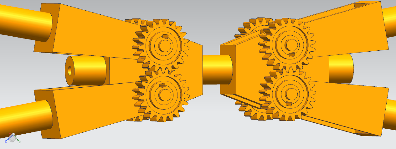
Further, the second second connecting rod comprises a second upper connecting rod and a second lower connecting rod, a gear shaft sleeve is arranged at one end of the second upper connecting rod and the second lower connecting rod and the second sliding connector, a keyway is arranged with the gear shaft sleeve, and the second upper connecting rod and the second lower connecting rod are fixedly connected through a keyway and a gear.
Further, the small pull rod is arranged in the same position, and the first upper pull rod and the first lower pull rod are symmetrical with respect to the central slide bar.
Further, the second upper connecting rod and the second lower connecting rod are fixedly connected with the gear with respect to the central slide rod symmetrically.
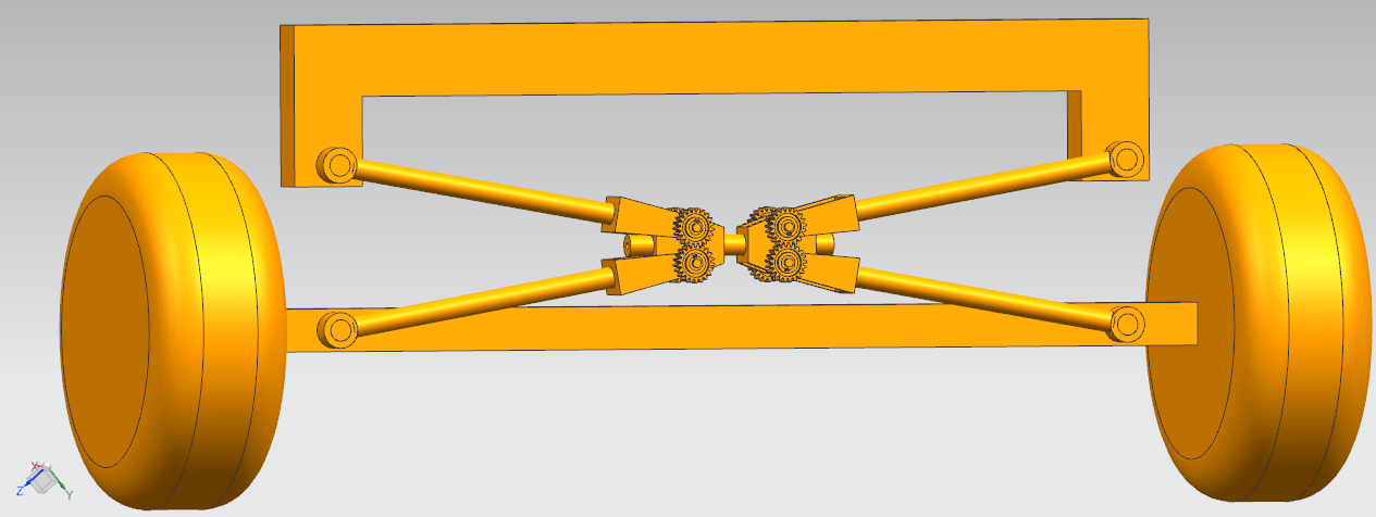
In the technical scheme provided above, compared with the prior art, at least the following beneficial effects or advantages are included: the hard bridge off-road vehicle with the present invention is installed, when the body moves up and down relative to the axle when driving at high speed on the undulating road surface, the end of the first two connecting rods and the end of the second two connecting rods are always in two parallel planes, that is to say, the body has no lateral displacement relative to the axle, so as to improve the comfort and safety of the vehicle; At the same time, the technical scheme of the present invention has a large stroke.
The present invention provides a vehicle, comprising a two-link type transverse thrust rod structure described above.
Description of the drawings
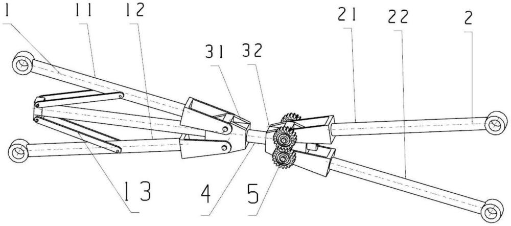
Fig. 1 is a schematic diagram of the structure of a two-link type transverse thrust rod according to the embodiment of the present application;
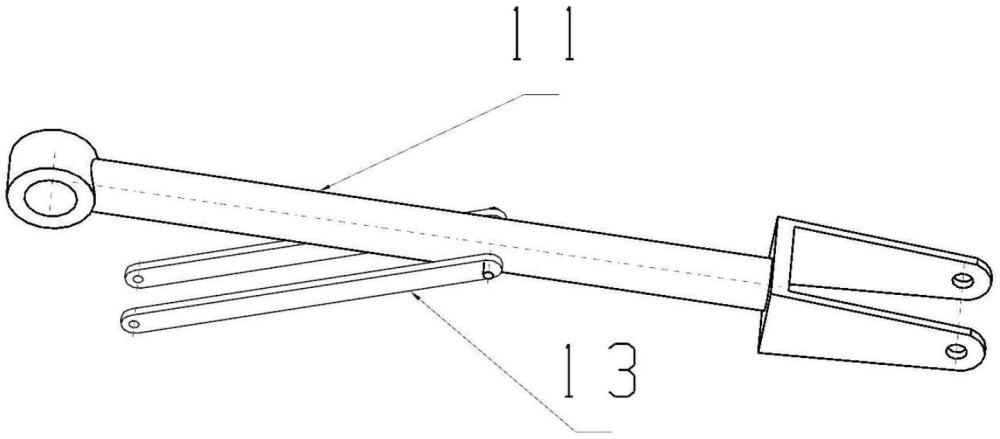
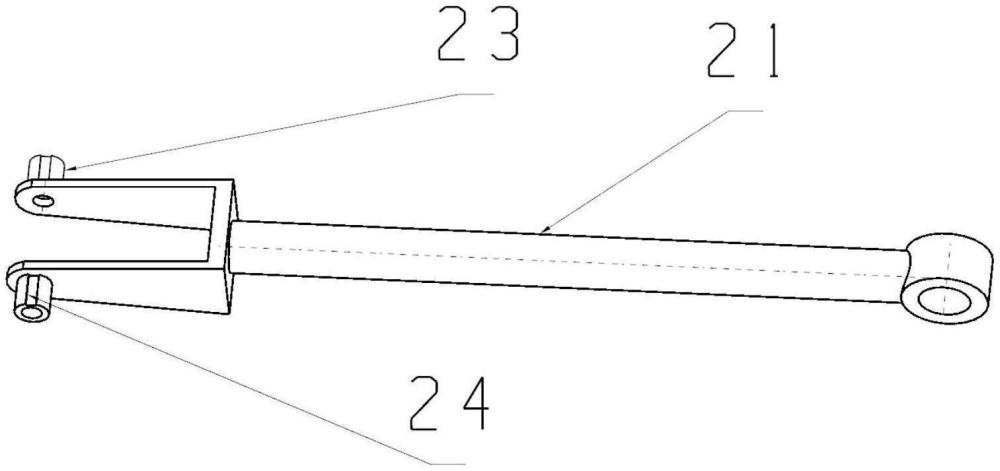
Fig. 2 is a schematic diagram of the structure of the first upper connecting rod according to the embodiment of the present application;
Fig. 3 is a schematic diagram of the structure of the second upper connecting rod according to the embodiment of the present application;
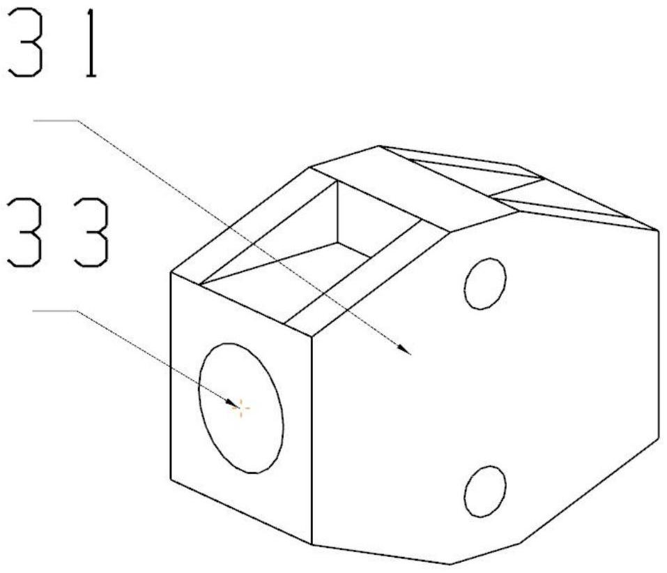
Fig. 4 is a schematic diagram of the first sliding connector according to the embodiment of the present application;
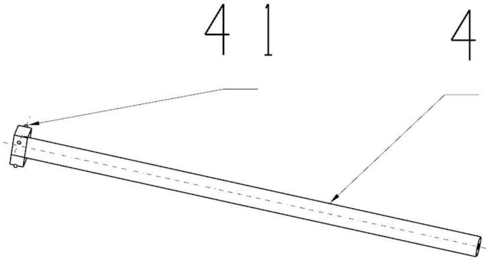
Fig. 5 is a schematic diagram of the structure of the central slide bar according to the embodiment of the present application;
The numbers in the drawings are:
1. a first two connecting rods; 11. a first upper connecting rod; 12. a first lower connecting rod; 13. a small pull rod;
2. a second and two connecting rods; 21. a second upper connecting rod; 22. a second lower connecting rod; 23. a gear bushing; 24. a keyway
31. a first sliding connector; 31. a second sliding connector; 33. a center hole;
4. a central slide bar; 41 connection points;
5. a gear
The specific embodiment
As shown in Figure 1-5, the two-link type transverse thrust rod of the present embodiment comprises: a central slide rod 4, and the central slide rod is configured with a connection point 41; the first sliding connector 31, the second sliding connector 32, the first sliding connector 31 and the second sliding connector 32 are provided with a central hole 33, and are slidably connected with the central slide rod 4 through the central hole 33; the first two connecting rods 1 are rotatably connected with the first two connecting rods 1 and the first sliding connector 31; the second second connecting rod 2 is rotatably connected with the first sliding connector 32.
The ends of the first upper connecting rod 11 and the second upper connecting rod 21 of the two-link type transverse thrust rod of the present embodiment are rotatably connected with the body cross member, the first lower connecting rod 12 and the second lower connecting rod 22 are rotatably connected with the axle, and when the body floats up and down, the first and second connecting rods 1 and the second second connecting rod 2 can swing respectively.
As an embodiment, the first second connecting rod 1 comprises a first upper connecting rod 11 and a first lower connecting rod 12, a small tie rod 13 is respectively arranged in the middle part of the first upper connecting rod 11 and the first lower connecting rod 12, the small tie rod 13 is rotatably connected with the first upper connecting rod 11 and the first lower connecting rod 12, and the other end of the small tie rod 13 is rotatably connected with the connecting point 41 on the central slide rod 4. When the wheels on one side of the first two connecting rods 1 move up and down relative to the car body, the angles between the first upper connecting rod 11 and the second lower connecting rod 12 of the first and second connecting rods 12 are reduced or expanded accordingly, and under the effect of the small tie rod 13, the angles of the first upper connecting rod 11 and the first lower connecting rod 12 are always equal relative to the central sliding rod 4.
As an embodiment, the second second connecting rod 2 comprises a second upper connecting rod 21 and a second lower connecting rod 22, a gear shaft sleeve 23 is arranged at one end of the second upper connecting rod 21 and the second lower connecting rod 22 and a second sliding connector 32, a gear shaft sleeve 23 is provided with a keyway 24, and the second upper connecting rod 21 and the second lower connecting rod 22 are fixedly connected through a keyway 24 and a gear 5. When the wheels on one side of the second second connecting rod 2 move up and down relative to the car body, the angles between the second upper connecting rod 21 and the second lower connecting rod 22 of the second second connecting rod 2 are reduced or expanded accordingly, and under the meshing effect of gear 5, the included angles of the second upper connecting rod 21 and the second lower connecting rod 22 are always equal with respect to the central sliding rod 4.
As an embodiment, the second second connecting rod 2 is connected with the gear 5 in a way that is fixed through a keyway 24 and can also be connected and fixed by welding or other means.
The above-mentioned embodiments are only the preferred embodiments of the present invention, and are only used to explain the present invention, not to limit the scope of the embodiment of the present invention, and for those skilled in the art, of course, other embodiments can be easily made by way of replacement or change according to the technical content disclosed in the present specification, so all changes and improvements made in the principles and process conditions of the present invention should be included in the scope of the patent application for the present invention.
A two-link type transverse thrust rod structure and vehicle










 400-4929-0909
 contact@catarc.com.cn