Content of the invention
In view of the defects of the prior art, the invention provides a self-centering multi-shaft linkage type internal expansion clamping mechanism which is used for fixing products by arranging a plurality of elastic pins on a mandrel of the internal expansion clamping mechanism. When in use, the plurality of elastic pins of the internal expansion clamping mechanism are simultaneously stressed, the inner wall expansion force of the product is uniform, and the positioning is accurate.
In order to achieve the above objects and other objects, the invention provides a self-centering multi-shaft linkage type internal expansion clamping mechanism.
Fixing base.
One end of the mandrel is fixedly arranged on the fixed seat, a mandrel through hole is formed in the center of the mandrel, and a plurality of insert mounting grooves are formed in the periphery of the mandrel.
A plurality of inserts are detachably connected with the insert mounting groove, and an elastic pin movable groove is formed in the upper part of the insert block.
The elastic pin is arranged in the pin mounting groove through the spring pin movable groove, and a spring pin inclined plane is arranged on the top of one side of the elastic pin close to the through hole of the mandrel.
The fixing block is detachably connected with the other end of the mandrel, and a blind hole is formed in the center of the fixing block.
The elastic part is arranged in the blind hole, and the upper end of the elastic piece is in contact with the fixed block.
The pin pressing block is fixedly connected with the lower end of the elastic piece and located in the through hole of the mandrel. The lower surface of the pin pressing block is provided with a pressing block inclined plane matched with the inclined plane of the elastic pin.
, The insert mounting grooves are T-shaped grooves, and the inserts slide into the T-shaped groove upper end and close to the mandrel.
, The number of the insert mounting grooves is 3 or more, and the insert mounting grooves are equally spaced along the periphery of the mandrel.
, The elastic member is a spring.
, The elastic end of the elastic pin is provided with an elastic washer.
, The center of the fixing seat is provided with a boss matched with the spindle through hole.
, A fixing hole is arranged on the fixing seat, and the fixing hole is used for fixing the clamping mechanism.
, The fixed block is provided with a screw hole which is connected with a screw hole arranged on the other end of the mandrel through a bolt.
, The mandrel through hole is a rounded through hole.
The invention further provides a clamping method applying the self-centering multi-shaft linkage type internal expansion clamping mechanism.
A product to be pressed and fixed is sleeved with a mandrel from the upper end of the internal expansion clamping mechanism.
A plurality of elastic pins are simultaneously sliding inwards by the product pressure, and the spring pin pressing block is jacked up through the inclined plane.
The spring pin pressing block is jacked up to cause the elastic piece to bear force and generate reverse pressure to press down the spring pin pressing block.
A plurality of elastic pins expand outwards after being stressed, and the product is internally expanded to press and fix the product.
In conclusion, the self-centering multi-shaft linkage type internal expansion clamping mechanism and the clamping method have the following beneficial effects: firstly, a plurality of elastic pins are stressed simultaneously, so that the inner wall of the product is uniform in expansion force and accurate in positioning. Secondly, after the internal expansion clamping mechanism of the invention is used for fixing the product, no indentation can be generated to the product. , The internal expansion clamping mechanism can be used for replacing the elastic piece according to the required elastic force and expanding the application range of the device. In addition, the internal expansion clamping mechanism is simple in structure. The device is convenient to process, can be used as auxiliary internal expansion and clamping of equipment such as most dies, tools and clamping tools, and can be used for fixing various special-shaped parts.
Mode of execution
Other advantages and efficiencies of the present invention will become apparent to those skilled in the art from the following detailed description, which, taken in conjunction with the accompanying drawings, illustrate embodiments of the invention. The present invention may be practiced or applied in other different specific embodiments, and the various details of the present specification may be modified or changed without departing from the spirit of the present invention, based on various aspects and applications.
It should be noted that the illustration provided in this embodiment illustrates only the basic idea of the present invention in a schematic manner, and only the components related to the present invention rather than the number, shape, and size of the components in actual practice are shown.
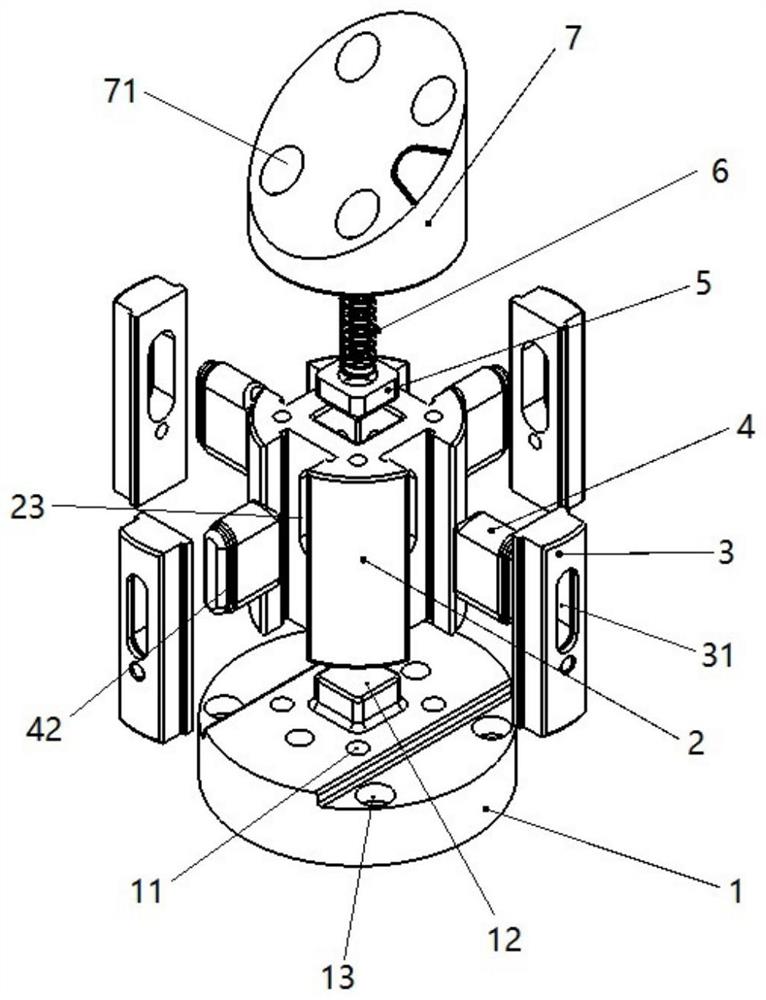
As shown 1 - and 4, the self-centering multi-shaft linkage type internal expansion clamping mechanism can comprise a fixed seat 1, a mandrel 2, an insert 3, a spring pin 4, a pin pressing block 5 and an elastic piece 6 and fixing block 7.
As shown 1. 1 Is a schematic structural view of an embodiment of a self-centering multi-axis linkage type internal expansion clamping mechanism according to the present invention, wherein a central shaft through hole 2 is formed in a central position of the mandrel 1, and a plurality of insert mounting grooves 2 are formed in the outer periphery of the mandrel 21 through a pin mounting groove 2 22 formed in the inner wall of the insert mounting groove 23 22. A plurality of inserts 3 are detachably mounted in a plurality of insert mounting grooves 22, and the insert 3 is provided with a pin moving groove 23 at a position corresponding to the pin mounting groove 31. A plurality of pin pins 4 pass through the pin movable slot 31 and are disposed within the pin mounting slot 23. The spring pin 4 is provided on the top of the side of the mandrel through hole 21 with a pin inclined surface 41. Fixed block 7 is detachably connected with other end of mandrel 2, and fixed block 2's central position is seted up a blind hole, and the opening direction of blind hole is towards the mandrel through-hole 21. The elastic member 6 is provided in the blind hole of the fixing block 2, and the upper end of the elastic member 6 abuts against the fixing block 6. The pin pressing block 5 is disposed in the spindle through hole and fixedly connected to the lower end of the elastic member 6, and the lower surface of the pin pressing block 5 is provided with a pressing block inclined surface 41 matching the pin inclined surface 51.
As 2, FIG. 4 shows. 2 Is a top view of an embodiment of a self-centering multi-shaft linkage type intumescent clamping mechanism according to the present invention, wherein the mandrel 4 is provided with a fixing base screw hole 2 and a fixing block screw hole 24 through which one end of the mandrel 1 is screwed with a fixing base screw hole on the fixing base 7. The spindle hole 11 is connected with the fixing block 71.2 through the mandrel screw hole 24 and the fixed block screw hole are respectively provided with a mandrel screw hole and a fixing base 1 7 on the fixing block 2 . 24Of course, in other embodiments. The connecting means may be varied, for example, a screw hole connected to the fixing base 2 and the fixing block 1 may be provided at both ends of the spindle 7 in a non-penetrating manner, respectively. For example, the mandrel 2 may be integrally formed with the fixed seat 1, while the other end of the mandrel 2 is screwed to the fixed block screw hole on the stationary block 24 by the spindle screw hole 7.
As 1. 2 Shows that, in the embodiment of the present invention, a boss 1 may be provided at the center of the holder 12, and the mandrel through hole 12 may be sleeved in the boss 21, and the boss 21 may be provided in the boss 12 to automatically align the spindle through hole 12 with the mandrel screw 2 at the position of the holder 1 such that it is convenient to assemble 1 the spindle 11 21 with the spindle through-hole set 24 screw 12.
As shown 2, in the embodiment of the present invention, the fixing seat 1 may be provided with a fixing hole 13 for fixing the whole device, for example, the device can be fixed on the assembly operation platform through the fixing hole 13 13, so that the device is prevented from moving, and the operation is convenient. The fixing holes 13 may be, for example, a plurality of fixing holes uniformly distributed around the fixing base. For example, 2 fixing holes 4 uniformly distributed along the circumference of the circular fixing base shown in FIG. 13 may be used, and other numbers of fixing holes 13 may be used. When the fixing base 1 is of another shape, the fixing holes 13 may be distributed in different shapes, such as a square fixing seat 1, and fixing holes 13 may be provided along four sides or opposite sides thereof.
As 2 and 4, the periphery of the mandrel 2 is provided with a plurality of insert mounting grooves 22, and the plurality of insert mounting grooves 22 may be equally spaced evenly along the outer circumference of the mandrel 2 or the like. The number of the insert mounting grooves 22 may be 3 or more, and 3 点 since @timetime@ can determine a circle, the unique center position can be determined, so that the clamping mechanism of the invention can be ensured to achieve accurate positioning. For example, 4 insert mounting grooves 22 shown in the figures may be used.
2 And 4, in the embodiment of the present invention, the insert mounting grooves 22 may be T-shaped grooves, i.e. side edges extending from the upper ends of the insert mounting grooves 3 are extended from the upper ends of the insert mounting groove portions 3 and the inserts 22 are engaged with the clamping portions extending from the two sides 3 of the insert mounting grooves to achieve the tightening of the insert T and the mandrel 3 2.
1 - And 4, the center of the mandrel 2 is provided with a spindle through hole 21, and the inner wall of the insert mounting groove 2 of the mandrel 22 and the corresponding position on the insert 3 are respectively provided with a pin mounting groove 23 and a pin movable groove 31, and elastic ends of the spring pin 31 4 4 are provided in the pin movable 31 groove 23. The spring pin 4, the pin mounting groove 23, and the pin movable groove 31 have the same height as the spring pin mounting groove 23 and larger than that of the spring pin 4, and the elastic end of the pin 4 has the same height as the pin moving groove 31 side away from the pin mounting groove 23.
When the clamping mechanism of the present invention is assembled, the elastic end of the pin 4 is first inserted into the pin mounting groove 23 and pushed along the pin mounting groove 23 centripetal axis through hole 21, so that the end surface of the spring pin 4 is not higher than the inner wall of the pin mounting groove 23 and then the insert 3 is aligned with the pin moving groove 22 along the pin mounting groove 23 31.
1 - And 4, the center of the mandrel 2 is provided with a spindle through hole 21, and the pin 4 is provided with a pin ramp 21 at the top of the spindle through hole 41, for example 41 at the lower end of the pin pressing block 45°. to match the pin inclined surface 21 of the pin 5 with the pin pressing block 5 at the lower end of 41 the spring pin press-hole 51 4, for example. When the pin block 5 is subjected to downward pressure, pressure is transmitted to the pin 51 through the compact ramp 4 such that the spring pin 4 is expanded outward by an outward force. , When pin 4 is subjected to an inward pressure, pressure is transmitted to pin block 41 through pin ramp 5 such that spring pin block 5 experiences an upward force and moves upward along the mandrel through hole.
1 - And 3, in the embodiment of the present invention, the elastic end of the pin 4 may be provided with an elastic washer 42, and the elastic washer 42 is provided at a position where the elastic end of the pin 4 comes into contact with the pin movable groove 3 of the insert 31.
1 - Is shown 3. The center of the fixing block 7 is provided with a blind hole, and the open end of the blind hole is provided on one side of the lower spring pin pressing block 5. An elastic member 6 is disposed in the blind hole, an upper end of the elastic member 6 abuts against the fixing block 7, and a lower end of the elastic member 6 is connected to the pin pressing block. When the product needs to be compacted and fixed, the upper end of the self-centering multi-axis linkage internal expanding clamping mechanism is sleeved with the mandrel 2, and then the plurality of pin 2 distributed along the periphery of the mandrel 4 are simultaneously slid into the mandrel through hole 21 and ejected through the pin inclined surface 41 to the spring pin pressing block 5 5 to force the elastic member 6 5 to shrink and generate reverse pressure. The elastic member 6 presses the pin pressing block 5 under the reverse pressure, and the pin pressing block 5 transmits the reverse pressure to the pin 51 through the pin inclined surface 4, the plurality of pin 4 are forced to slide outwards, and the product is internally expanded to press and fix the product.
As shown 2, in the embodiment of the present invention, the mandrel through hole 21 may be square in order to facilitate the up-and-down movement of the pin block 5 within the mandrel through hole 21, the mandrel through hole 21 may be a rounded through hole as shown in the figure, and the pin compact 5 may be a rounded square that matches it. In other embodiments, the mandrel through hole 21 may also be other polygonal or circular.
As 1. As shown 3, in the embodiment of the present invention, a groove 5 may be provided at the joint between the upper surface of the pin pressing block 6 and the elastic member 52, and the lower end of the elastic member 6 is disposed in the groove 52. Positioning the lower end of the elastic member 6 in the groove 52 prevents the lower end of the elastic member 6 from moving on the upper surface of the pin pressing block 5, resulting in a change in the stress direction on the elastic member 6, thereby affecting the accuracy of the device fixing product.
As shown 3, in the embodiment of the invention, an elastic member fixing member 5 may be provided above the pin pressing block 8, and the elastic member 6 is fixed to the pin pressing block 8 by the elastic member fixing member 5, for example, within the groove 52. The elastic member fixing member 8 may be, for example, a fixing pin penetrating the lower end of the elastic member 6 and two ends fixed on the upper surface of the pin pressing block 5, respectively. In other embodiments of the present invention, the elastic member fixing member 8 may be, for example, a fixing sheet or the like.
As shown 1-3, in the embodiment of the present invention, the elastic member 6 may be a spring such as a coil spring, a pressure spring tube, or the like, and the elastic member 6 may be another elastic member such as a leaf spring, a bellows, or the like.
The invention further provides a clamping method applying the self-centering multi-shaft linkage type internal expansion clamping mechanism.
A product to be pressed and fixed is sleeved with a mandrel from the upper end of the self-centering multi-shaft linkage type internal expansion clamping mechanism.
A plurality of elastic pins are pressed inwards by the pressure of the inner wall of the product, and the pressure is transmitted to the spring pin pressing block through the elastic pin inclined plane.
The spring pin pressing block is jacked up to cause the elastic piece to bear force and generate reverse pressure to press down the spring pin pressing block.
A plurality of elastic pins expand outwards after being stressed, and the product is internally expanded to press and fix the product.
To the self-centering multi-shaft linkage type internal expansion clamping mechanism and the clamping method, a plurality of elastic pins are arranged on the mandrel of the internal expansion clamping mechanism to fix the product. , After the internal expansion clamping mechanism is used for fixing the product, no indentation can be generated to the product, and the product cannot be damaged. In addition, the internal expansion clamping mechanism can be used for replacing the elastic piece according to the required elastic force, and the application range of the device is wide. In addition, the internal expansion clamping mechanism is simple in structure. The device is convenient to process, can be used as auxiliary internal expansion and clamping of equipment such as most dies, tools and clamping tools, and can be used for fixing various special-shaped parts.
It should be understood by those skilled in the art that and the above description is not limited to the specific combinations of technical features described above, but it should be understood by those skilled in the art that other technical solutions formed by any combination of the above-described technical features or equivalent features thereof may be replaced with other technical features disclosed in the present application (but not limited to) having similar functions.
In addition to the technical features described in the specification, other technical features are known to those skilled in the art, and the other technical features will not be described in detail herein for the purpose of highlighting the innovative features of the present invention.


 400-4929-0909
 contact@catarc.com.cn

