Contents of the invention
The present invention is intended to solve at least one of the technical problems existing in the prior art. To this end, the first aspect of the present invention proposes a visualization processing method for point cloud data, the method comprising:
Determine the viewfield corresponding to the point cloud data according to the attribute information of the point cloud data to be processed, and determine the projection of the viewfield on the flat point cloud grid corresponding to the point cloud data, and obtain the field of view corresponding to the point cloud data;
The point cloud mesh within the coverage area of the event horizon is obtained, and the first set of point cloud meshes is obtained;
The area comprising the event horizon is divided into a concentric ring of the first quantity layer, and the concentric ring is centered on the center of the event horizon;
Based on the real-time frame rate of the computer, determine the actual number of point clouds that each of the first point cloud mesh can currently load, and load the point cloud data of the actual number of point clouds into the memory of the computer in a hierarchical manner according to the concentric rings;
The loaded point cloud data is rendered one by one, and the visual display result of the point cloud data to be processed is obtained.
Optionally, the determination of the actual number of point clouds currently loaded by each of the first point cloud meshes, comprising:
Determine the desired loading weights corresponding to the layer of the target concentric ring currently to be loaded and the multiple candidate loading weights corresponding to the expected loading weights;
The distance between each second point cloud grid included in the concentric ring of the target and the viewpoint is obtained respectively, and the target distance is obtained;
Obtain the number of point clouds included in each of the second point cloud meshes to obtain the second quantity;
Based on the expected loading weight, the candidate loading weight, the target distance, the second quantity, and the real-time frame rate of the computer, determine the actual number of point clouds in the second point cloud grid that the computer can load.
Optionally, the actual number of point clouds in the second point cloud grid capable of loading by the computer is determined based on the expected loading weight, the candidate loading weight, the target distance, the second quantity, and the frame rate of the computer in real time, comprising:
According to the total number of point clouds of the current layer and the candidate loading weight, determine the display number of point clouds corresponding to each candidate loading weight, and obtain a plurality of candidate loading quantities;
According to the real-time loading speed of the computer, determine the candidate time corresponding to the loading number of candidate loading number point cloud data, and obtain a plurality of candidate time time;
Select at least one target candidate time consuming less than the refresh time of the computer from the plurality of candidate time; The refresh time is determined according to the real-time frame rate;
The current actual loading weight is obtained by interpolating from the target candidate loading weight corresponding to the time taken by at least one target candidate;
According to the actual loading weight, the target distance and the second quantity, determine the actual number of point clouds in the second point cloud grid that the computer can load.
Optionally, the actual number of point clouds in the second point cloud grid capable of being loaded by the computer is determined according to the actual loading weight, the target distance, and the second quantity, comprising:
According to the target distance and distance coefficient, the target relationship distance is obtained;
According to the product of the target relationship distance and the actual loading weight, the consumption coefficient is obtained;
Take the smaller value of the consumption factor and 1 to obtain the incremental expectation;
According to the product of the second quantity and the expected increment, the actual number of point clouds in the second point cloud grid that the computer can load is obtained.
Optionally, the actual number of point cloud data is loaded into the memory of the computer in layers according to the concentric rings, comprising:
Determine the second grid number of each second point cloud mesh included in the concentric ring of the target;
determine the target index information corresponding to the second mesh number, and obtain the target position of the actual number of point cloud data from the point cloud storage file in accordance with the target index information;
The point cloud data of the target location is loaded into the memory of the said computer.
Optionally, the viewport corresponding to the point cloud data is determined according to the attribute information of the point cloud data to be processed, comprising:
Obtain the attribute information of the point cloud data to be processed from the point cloud index file, the attribute information includes the origin coordinates of the grid coordinate system corresponding to the point cloud data, the edge length of the point cloud mesh, the maximum number of the planar point cloud mesh, and the maximum Z-axis coordinates of the point cloud data;
Determine the initial coordinates of the viewpoint of the point cloud data according to the origin coordinates of the grid coordinate system, the edge length of the point cloud mesh, the maximum number of the flat point cloud mesh, the maximum Z-axis coordinates and the relative height of the Z coordinate of the preset viewpoint;
The viewpoint coordinate system is constructed by taking the initial coordinates of the viewpoint as the origin of the coordinate system;
The window of view formed by the angle of the X and Y axes in the viewpoint coordinate system is determined as the viewport;
The direction of the line vector from the viewpoint to the center of the viewport is determined as the direction of view;
The stereoscopic pattern composed of the viewpoint and the viewport in the direction of the direction of sight is determined as the viewport corresponding to the point cloud data.
Optionally, before rendering the loaded point cloud data one by one, it also includes:
Culling point cloud data outside the viewable area in the current view.
Optionally, if the current view is an orthographic view, the point cloud data outside the viewable area under the current view at least comprises:
The point cloud mesh outside the Okato projection area of the viewfinder includes point cloud data, the viewport and the window view ratio is greater than the first preset ratio and the distance from the center of the viewing angle to the center of the point cloud grid is greater than the first preset distance, the point cloud data included in the viewfield and the window view ratio is greater than the second preset ratio.
Optionally, if the current view is a free view, the point cloud data outside the viewable area under the current view at least comprises:
The point cloud data included in the point cloud mesh in the area other than the viewport, the point cloud data included in the point cloud mesh where the distance from the center of the point cloud grid to the viewpoint is greater than the third distance, and all the point cloud data when the distance from the viewpoint to the center of the viewfield is greater than the second preset distance; The third distance is the sum of the distance from the center of the viewview to the viewpoint and the preset reference distance.
Optionally, the loaded point cloud data is rendered one by one, comprising:
The point cloud data is rendered one by one using vertex shaders and fragment shaders.
Optionally, after obtaining the visual presentation of the point cloud data to be processed, it also includes:
When the orientation of the viewport and the distance from the viewpoint to the point cloud in the viewfield are detected, the attribute information of the point cloud data is re-obtained, and new attribute information is obtained;
determine the new field of view corresponding to the point cloud data according to the new attribute information, and determine the projection of the new field of view on the plane point cloud grid corresponding to the point cloud data, and obtain the new horizon corresponding to the point cloud data;
The point cloud mesh within the coverage area of the new horizon is obtained, and the third set of point cloud meshes is obtained;
The newly added point cloud data in the third point cloud mesh collection is loaded into the memory.
Optionally, the newly added point cloud data in the third point cloud mesh collection is loaded into the memory, comprising:
obtain the first mesh number of the point cloud mesh in the first point cloud mesh set, and the third mesh number of the point cloud mesh in the third point cloud mesh set;
obtain a differential grid number existing in the first grid number and not present in the third grid number, obtain a new grid number that does not exist in the first grid number, but exist in the third grid number, and obtain the same grid number existing in both the first grid number and the third grid number;
From the point cloud data that has been loaded into the memory, the point cloud data corresponding to the differential mesh number is deleted, the point cloud data corresponding to the same mesh number is retained, and the new point cloud data is loaded.
The second aspect of the present invention proposes a visualization processing device for point cloud data, the apparatus comprising:
The horizon determination module is configured to determine the viewport corresponding to the point cloud data according to the attribute information of the point cloud data to be processed, and to determine the projection of the viewfield on the flat point cloud grid corresponding to the point cloud data, and obtain the horizon corresponding to the point cloud data;
The first point cloud mesh collection acquisition module is used to obtain the point cloud mesh within the coverage area of the event horizon to obtain the first point cloud grid set;
a concentric ring division module for dividing the region comprising the event horizon into a concentric ring of the first quantity layer, and the concentric ring takes the center of the event horizon as the center of the circle;
The hierarchical loading module is configured to determine the actual number of point clouds that each of the first point cloud meshes can currently load based on the real-time frame rate of the computer, and the point cloud data of the actual number of point clouds is loaded into the memory of the computer in order according to the concentric rings;
The rendering processing module is used to render the loaded point cloud data one by one, and obtain the visual display result of the point cloud data to be processed.
Optionally, the layered loading module is specifically used for:
Determine the desired loading weights corresponding to the layer of the target concentric ring currently to be loaded and the multiple candidate loading weights corresponding to the expected loading weights;
The distance between each second point cloud grid included in the concentric ring of the target and the viewpoint is obtained respectively, and the target distance is obtained;
Obtain the number of point clouds included in each of the second point cloud meshes to obtain the second quantity;
Based on the expected loading weight, the candidate loading weight, the target distance, the second quantity, and the real-time frame rate of the computer, determine the actual number of point clouds in the second point cloud grid that the computer can load.
Optionally, the layered loading module is further used for:
According to the total number of point clouds of the current layer and the candidate loading weight, determine the display number of point clouds corresponding to each candidate loading weight, and obtain a plurality of candidate loading quantities;
According to the real-time loading speed of the computer, determine the candidate time corresponding to the loading number of candidate loading number point cloud data, and obtain a plurality of candidate time time;
Select at least one target candidate time consuming less than the refresh time of the computer from the plurality of candidate time; The refresh time is determined according to the real-time frame rate;
The current actual loading weight is obtained by interpolating from the target candidate loading weight corresponding to the time taken by at least one target candidate;
According to the actual loading weight, the target distance and the second quantity, determine the actual number of point clouds in the second point cloud grid that the computer can load.
Optionally, the layered loading module is further used for:
According to the target distance and distance coefficient, the target relationship distance is obtained;
According to the product of the target relationship distance and the actual loading weight, the consumption coefficient is obtained;
Take the smaller value of the consumption factor and 1 to obtain the incremental expectation;
According to the product of the second quantity and the expected increment, the actual number of point clouds in the second point cloud grid that the computer can load is obtained.
Optionally, the layered loading module is further used for:
Determine the second grid number of each second point cloud mesh included in the concentric ring of the target;
determine the target index information corresponding to the second mesh number, and obtain the target position of the actual number of point cloud data from the point cloud storage file in accordance with the target index information;
The point cloud data of the target location is loaded into the memory of the said computer.
Optionally, the horizon determination module is specifically used for:
Obtain the attribute information of the point cloud data to be processed from the point cloud index file, the attribute information includes the origin coordinates of the grid coordinate system corresponding to the point cloud data, the edge length of the point cloud mesh, the maximum number of the planar point cloud mesh, and the maximum Z-axis coordinates of the point cloud data;
Determine the initial coordinates of the viewpoint of the point cloud data according to the origin coordinates of the grid coordinate system, the edge length of the point cloud mesh, the maximum number of the flat point cloud mesh, the maximum Z-axis coordinates and the relative height of the Z coordinate of the preset viewpoint;
The viewpoint coordinate system is constructed by taking the initial coordinates of the viewpoint as the origin of the coordinate system;
The window of view formed by the angle of the X and Y axes in the viewpoint coordinate system is determined as the viewport;
The direction of the line vector from the viewpoint to the center of the viewport is determined as the direction of view;
The stereoscopic pattern composed of the viewpoint and the viewport in the direction of the direction of sight is determined as the viewport corresponding to the point cloud data.
Optionally, the apparatus further comprises:
Culling module, which culls point cloud data outside the viewable area in the current view.
Optionally, if the current view is an orthographic view, the point cloud data outside the viewable area under the current view at least comprises:
The point cloud mesh outside the Okato projection area of the viewfinder includes point cloud data, the viewport and the window view ratio is greater than the first preset ratio and the distance from the center of the viewing angle to the center of the point cloud grid is greater than the first preset distance, the point cloud data included in the viewfield and the window view ratio is greater than the second preset ratio.
Optionally, if the current view is a free view, the point cloud data outside the viewable area under the current view at least comprises:
The point cloud data included in the point cloud mesh in the area other than the viewport, the point cloud data included in the point cloud mesh where the distance from the center of the point cloud grid to the viewpoint is greater than the third distance, and all the point cloud data when the distance from the viewpoint to the center of the viewfield is greater than the second preset distance; The third distance is the sum of the distance from the center of the viewview to the viewpoint and the preset reference distance.
Optionally, the rendering processing module is specifically used for:
The point cloud data is rendered one by one using vertex shaders and fragment shaders.
Optionally, the apparatus further comprises:
A new attribute information acquisition module for re-obtaining attribute information of the point cloud data and obtaining new attribute information when the orientation of the viewport and the distance from the viewpoint to the point cloud in the viewport are detected;
The new horizon determination module is configured to determine the new field of view corresponding to the point cloud data according to the new attribute information, and to determine the projection of the new field of view on the plane point cloud grid corresponding to the point cloud data, and obtain the new horizon corresponding to the point cloud data;
The third point cloud mesh collection acquisition module is used to obtain the point cloud mesh within the coverage range of the new horizon, and the third point cloud mesh set is obtained;
A new point cloud data loading module for loading the newly added point cloud data in the third point cloud mesh collection into the memory.
Optionally, the new point cloud data loading module is specifically used for:
obtain the first mesh number of the point cloud mesh in the first point cloud mesh set, and the third mesh number of the point cloud mesh in the third point cloud mesh set;
obtain a differential grid number existing in the first grid number and not present in the third grid number, obtain a new grid number that does not exist in the first grid number, but exist in the third grid number, and obtain the same grid number existing in both the first grid number and the third grid number;
From the point cloud data that has been loaded into the memory, the point cloud data corresponding to the differential mesh number is deleted, the point cloud data corresponding to the same mesh number is retained, and the new point cloud data is loaded.
The third aspect of the present invention proposes an electronic device, the electronic device includes a processor and a memory, the memory type stores at least one instruction, at least one program, code set or instruction set, the at least one instruction, at least one program, the code set or instruction set is loaded and executed by the processor to achieve a visual processing method of point cloud data as described in the first aspect.
The fourth aspect of the present invention proposes a computer-readable storage medium in which at least one instruction, at least one program, code set or instruction set is stored, and at least one instruction, at least one program, the code set or instruction set is loaded and executed by the processor to achieve a visual processing method of point cloud data as described in the first aspect.
Embodiments of the present invention have the following beneficial effects:
In the embodiment of the present invention, the viewport corresponding to the point cloud data is determined according to the attribute information of the point cloud data to be processed, and the projection of the viewfield on the plane point cloud grid corresponding to the point cloud data is determined, and the horizon corresponding to the point cloud data is obtained; The point cloud mesh within the coverage area of the event horizon is obtained, and the first set of point cloud meshes is obtained; The area comprising the event horizon is divided into a concentric ring of the first quantity layer, and the concentric ring is centered on the center of the event horizon; Based on the real-time frame rate of the computer, determine the actual number of point clouds that each of the first point cloud mesh can currently load, and load the point cloud data of the actual number of point clouds into the memory of the computer in a hierarchical manner according to the concentric rings; The loaded point cloud data is rendered one by one, and the visual display result of the point cloud data to be processed is obtained. Based on the real-time frame rate of the computer, the above scheme determines the actual number of point clouds that the first point cloud mesh can load, and loads and renders them hierarchically according to the concentric rings, which can ensure that the point cloud data is safely loaded and rendered without delay, stuttering and operation crash without delay, stuttering and operation crash, and improves the processing ability of point cloud data.
Additional aspects and advantages of the present invention will be given in part in the following description, and some will become apparent from the following description, or learned through the practice of the present invention.
Specific embodiment
The following will be combined with the accompanying drawings in the embodiment of the present invention, the technical solution in the embodiment of the present invention is clearly and completely described, obviously, the described embodiment is only a partial embodiment of the present invention, not all embodiments. Based on embodiments of the present invention, all other embodiments obtained by those of ordinary skill in the art without performing inventive work fall within the scope of protection of the present invention.
The present specification provides a method operation steps as described in embodiments or flowcharts, but based on routine or uncreative labor may include more or fewer operation steps. In the actual system or server product execution, may be executed sequentially or in parallel according to the method shown in the embodiment or the accompanying figure (e.g., parallel processor or multithreaded environment).
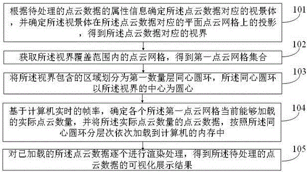
FIG 1 is a step flow chart of a visualization processing method of the first point cloud data provided by an embodiment of the present invention. The method can include the following steps:
Step 101: Determine the viewfield corresponding to the point cloud data according to the attribute information of the point cloud data to be processed, and determine the projection of the viewfield on the plane point cloud grid corresponding to the point cloud data, and obtain the corresponding horizon of the point cloud data.
The point cloud data to be processed refers to the point cloud data stored in the point cloud storage file and to be visualized. The point cloud storage file corresponds to the point cloud index file, and the point cloud index file is used to indicate the storage location of each point cloud data in the point cloud storage file, as well as to mark the various attribute information of the point cloud data.
The point cloud data is stored in the form of a point cloud mesh, and the division method of the point cloud mesh can be: first determine the geometric boundary of the point cloud data, obtain the outer frame covering the point cloud data according to the geometric boundary, and then select the appropriate first side length, take the first side length as the side length of the square mesh, and divide the outer frame into multiple point cloud meshes, so as to obtain multiple point cloud meshes corresponding to the point cloud data, and a large amount of point cloud data is stored in each point cloud mesh.
The attribute information of the point cloud data is obtained from the point cloud index file, and the viewpoint coordinates where the camera is located can be determined through the attribute information, the viewpoint coordinate system is obtained through the viewpoint coordinates, and then the viewport formed by the angle of the X axis and the Y axis coordinate axis under the viewpoint coordinate system is obtained, that is, the viewport, which is further obtained by the viewport, and the three-dimensional shape composed of the viewpoint and the viewport in the direction of the viewpoint is determined as the viewfinder. The projection of the viewscape on the flat point cloud mesh is the field of view corresponding to the point cloud data.
FIG 2 is a schematic view of the point cloud mesh provided by an embodiment of the present invention.
Referring to Figure 2, P0 is the boundary datum point, surrounded by the X and Y axes of the coordinate system to form a bounding box covering all point cloud data. Dividing the area contained in the bounding box into multiple square meshes according to the length of the first side, which results in multiple point cloud meshes in Figure 2.
FIG 3 is a schematic view of the viewpoint coordinate system provided by an embodiment of the present invention.
Referring to Figure 3, V is the viewpoint, and the angle of the X and Y axes and the line connecting V in the viewpoint coordinate system constitute the field of view window ABCD, that is, the viewport. ABCD is round. The direction of the line vector from viewpoint V to the center E of the ABCD circle is the direction of view. The viewfinder V_ABCD can be obtained from viewpoint V, viewport ABCD, and gaze direction information.
FIG 4 is a schematic view of the point cloud mesh, the field of view and the horizon in the P0 coordinate system provided by the embodiment of the present invention.
Referring to Figure 4, P0 is the boundary datum point, surrounded by the X and Y axes of the coordinate system to form a bounding box covering all point cloud data. The projection of the viewfinder V_ABCD on a planar point cloud grid is A'B'C'D', i.e. A'B'C'D' is the corresponding field of view for the point cloud data. In orthographic view, A'B'C'D' is circular, and in free view, A'B'C'D' is oval.
Step 102, obtain the point cloud mesh within the coverage area of the event horizon, and obtain the first point cloud mesh collection.
According to the coordinates of the point cloud data and the coordinate range of the event horizon, the point cloud data within the coverage area of the event horizon can be obtained, and the point cloud grid to which these point cloud data belong can be further obtained, and the collection of these point cloud meshes constitutes the first point cloud mesh collection.
Step 103, the area comprising the event horizon is divided into a concentric ring of the first quantity layer, and the concentric ring is centered on the center of the event horizon.
The horizon contains areas that are circular. Specifically, a first layer of concentric rings is created within A'B'C'D', centered on the center of the event horizon.
The first quantity can be set according to the size of the area contained by the horizon. For example, it can be set to 10 or 30, etc. The radius of each layer of concentric rings or the ring width of the concentric rings can be set based on the density of the point cloud data.
Exemplifyingly, the area contained in the event horizon is divided into 30 layers of concentric rings. The first concentric ring is a circular area with a radius of 10 meters, the outer ring of the 30th layer is an infinity area, and the other concentric rings are all 30 meters wide.
FIG 5 is a schematic view of the concentric rings provided by embodiments of the present invention.
Referring to Figure 5, the horizon is divided into seven layers of concentric rings, each consisting of a point cloud mesh shown in S1. During subsequent point cloud data loading and rendering, the point cloud data within the point cloud mesh contained by each concentric ring is processed hierarchically and gradually.
Step 104, based on the real-time frame rate of the computer, determine the actual number of point clouds that each of the first point cloud mesh can currently load, and the point cloud data of the actual number of point clouds is loaded into the memory of the computer in order according to the concentric rings.
The frame rate of the computer refers to the refresh rate of the computer monitor, and the frame rate is measured in times / second, that is, the number of screen refreshes in one second. The reciprocal of the frame rate is the time required for the computer to refresh once, that is, a single time consumption.
If the time required by the computer to load a batch of point cloud data is less than a single time, there will be no stuttering of the picture. Depending on the current performance of the computer, the time it takes for the computer to load a point cloud data can be obtained. Therefore, with a single time as a limitation, the actual number of point clouds that the computer can currently load at one time can be obtained.
According to the hierarchical loading rule of loading one concentric ring at a time, the actual number of point clouds is the number of point clouds that can be loaded in the concentric rings currently to be loaded.
According to the current number of point clouds that can be loaded by concentric rings, loading and rendering in layers can ensure that the point cloud data is safely loaded and rendered without delay, stuttering and running crash without delay, stuttering and running crash, and improving the processing power of point cloud data.
Step 105: render the loaded point cloud data one by one, and obtain the visual display result of the point cloud data to be processed.
After the point cloud data on the concentric rings of the current level is loaded into the computer memory, the newly loaded point cloud data can be rendered one by one to obtain a visual display result for users to view.
In summary, in an embodiment of the present invention, the viewfield corresponding to the point cloud data is determined according to the attribute information of the point cloud data to be processed, and the projection of the viewfield on the plane point cloud grid corresponding to the point cloud data is determined, and the corresponding horizon of the point cloud data is obtained; The point cloud mesh within the coverage area of the event horizon is obtained, and the first set of point cloud meshes is obtained; The area comprising the event horizon is divided into a concentric ring of the first quantity layer, and the concentric ring is centered on the center of the event horizon; Based on the real-time frame rate of the computer, determine the actual number of point clouds that each of the first point cloud mesh can currently load, and load the point cloud data of the actual number of point clouds into the memory of the computer in a hierarchical manner according to the concentric rings; The loaded point cloud data is rendered one by one, and the visual display result of the point cloud data to be processed is obtained. Based on the real-time frame rate of the computer, the above scheme determines the actual number of point clouds that the first point cloud mesh can load, and loads and renders them hierarchically according to the concentric rings, which can ensure that the point cloud data is safely loaded and rendered without delay, stuttering and operation crash without delay, stuttering and operation crash, and improves the processing ability of point cloud data.
FIG 6 is a flowchart of the procedure for determining the field of view provided by an embodiment of the present invention. The method can include the following steps:
Step 201, obtain the attribute information of the point cloud data to be processed from the point cloud index file, the attribute information includes the origin coordinates of the grid coordinate system corresponding to the point cloud data, the edge length of the point cloud mesh, the maximum number of the planar point cloud mesh, and the maximum Z-axis coordinates of the point cloud data.
The point cloud index file includes the index information of the entire point cloud data and the index information of each point cloud mesh, and the index information of the point cloud data includes: the origin coordinates of the grid coordinate system, the point cloud mesh edge length h, the maximum coordinates![]()
![]() of the point cloud data on the Z axis, and the largest grid number
of the point cloud data on the Z axis, and the largest grid number![]() .
.
Step 202, according to the origin coordinates of the mesh coordinate system, the edge length of the point cloud mesh, the maximum number of the plane point cloud mesh, the maximum Z coordinate and the relative height of the Z coordinate of the preset viewpoint, determine the initial coordinates of the viewpoint of the point cloud data.
Specifically, the initial coordinates![]() of viewpoint V are calculated as follows:
of viewpoint V are calculated as follows:
![]() (1)
(1)
Among them, the origin coordinates P0 and h of the mesh coordinate system are the edge length of the point cloud mesh, which is the maximum number of the planar point cloud mesh, the maximum Z axis coordinates, and![]() the relative height of the
the relative height of the![]() Z coordinate of the
Z coordinate of the![]()
![]() preset viewpoint.
preset viewpoint. ![]() It can be set according to human experience, for example, ,,
It can be set according to human experience, for example, ,,![]()
![]() .
.
Step 203: Take the initial coordinates of the viewpoint as the origin of the coordinate system to construct the viewpoint coordinate system.
Take the initial coordinate of viewpoint V as the origin of the coordinate system, and construct the viewpoint coordinate![]() system XVY according to the customized X and Y axis directions.
system XVY according to the customized X and Y axis directions.
As shown in Figure 3, the coordinate system corresponding to XVY is the viewpoint coordinate system.
According to artificial experience, the length of the X and Y axes of the viewport in the viewpoint V coordinate system is set to Lvx and Lvy, respectively (Lxv=Lvy in this patent). The direction of the line vector from viewpoint V to the center E of the ABCD circle is called the direction of sight, and the direction of sight is expressed by the rotation angle (roll, pitch, yaw) of the V coordinate system (X, Y, Z) coordinate axis, and the initial direction of sight is set to the negative direction along the Z axis under the point cloud P0 coordinate system.
Step 204, the angle of view in the X axis and Y axis direction of the viewpoint coordinate system is determined as the viewport.
Step 205, the direction of the line vector from the viewpoint to the center of the viewport is determined as the direction of view.
Step 206, the viewpoint and the viewport in the direction of the direction of the three-dimensional pattern, determined as the point cloud data corresponding to the viewport.
Steps 204 and 206 may refer to FIG. 3. In Figure 3, V is the viewpoint, and the angle of the X and Y axes and the line of V in the viewpoint coordinate system form the field of view window ABCD, that is, the viewport. ABCD is round. The direction of the line vector from viewpoint V to the center E of the ABCD circle is the direction of view. The viewfinder V_ABCD can be obtained from viewpoint V, viewport ABCD, and gaze direction information.
FIG 7 is a step-by-step flowchart provided by an embodiment of the present invention to determine the actual number of point clouds currently capable of loading. The method can include the following steps:
Step 301, determine the desired loading weight corresponding to the layer of the target concentric ring to be loaded and a plurality of candidate loading weights corresponding to the expected loading weight.
According to the principle of near large and far small, the concentric rings close to the viewpoint are located nearby, and the density of the point cloud data that can be displayed can be set larger, while the concentric rings far away from the viewpoint are located at a distance, and the density of the point cloud data that can be displayed can be set smaller.
After the computer loads the point cloud data, it displays the loaded point cloud data. Therefore, the expected loading weight corresponding to each layer of concentric rings can be set in advance, with concentric rings close to the viewpoint expected to have a larger loading weight and concentric rings farther away from the viewpoint having a smaller expected loading weight.
The expected loading weight is based on the assumption that the computer can load an infinite number of point cloud data, but in practice, the amount of point cloud data that the computer can load is related to the computer's memory and current health status, so multiple levels of candidate loading weights can be set at the same time, and the candidate loading weight can be smaller than the expected loading weight or greater than the expected loading weight. Based on the current state of the computer, the candidate load weights can be used to determine the most appropriate load weight that satisfies the concentric rings currently to be loaded.
Exemplary, Table 1 is an embodiment of the present invention provided with a table of expected loading weight parameters.
Table 1 Expected to load the weight parameter table
![]()
Referring to Table 1, the number of layers of the concentric ring is 30 layers, min is the distance of the inner circle of the concentric ring from the viewpoint, max is the distance of the outer circle of the concentric ring from the viewpoint, quality is the expected loading weight, and ModelCoeffs is the initial empirical value of the consumption coefficient. where the consumption factor represents the quotient of the number of point clouds that the point cloud mesh can actually load and the total number of point clouds included in the point cloud mesh.
Exemplary, Table 2 is a multi-level candidate loading weight table provided by embodiments of the present invention.
Table 2 Multi-level candidate load weight parameter table
![]()
Referring to Table 2, the level of candidate loading weights is divided into five levels, and quality represents the expected loading weight. Among them, the first 3 levels of candidate loading weight are smaller than the expected loading weight, the 4th level is the same as the expected loading weight, and the 5th level is twice the expected loading weight.
Target concentric rings are concentric rings that are currently to be loaded. Assuming that the target concentric ring is a layer 5 concentric ring, the expected loading weight of the target is 0.00625 according to Table 1, and the candidate loading weights of the corresponding five levels are: 0.00625/20, 0.00625/8, 0.00625/2, 0.00625, 0.00625*2.
Step 302, respectively, obtain the distance between each second point cloud grid included in the target concentric ring and the viewpoint, and obtain the target distance.
The target concentric torus includes multiple point cloud meshes, which are referred to as the second point cloud mesh. Get the distance between the center of each second point cloud mesh and the viewpoint, which is the center of the concentric ring, to get multiple target distances.
FIG 8 is a schematic diagram of the target distance provided by an embodiment of the present invention. Referring to Figure 8, the length corresponding to Dist represents the target distance between the center of the point cloud mesh and the viewpoint.
Step 303, obtain the number of point clouds included in each of the second point cloud meshes, to obtain the second quantity.
The index information of a point cloud mesh is [(m,n), N], where (m,n) represents the mesh number and N represents the number of point clouds in the point cloud mesh. Therefore, the number of point clouds included in each second point cloud mesh can be obtained from the index information of the point cloud mesh, and the second quantity can be obtained.
Step 304, based on the expected loading weight, the candidate loading weight, the target distance, the second quantity, and the real-time frame rate of the computer, determine the actual number of point clouds in the second point cloud grid that the computer can load.
If the time taken by the computer to load a batch of point cloud data is less than a single time, there will be no stuttering and delay of the screen. Depending on the current performance of the computer, the time it takes for the computer to load a point cloud data can be obtained. Therefore, with a single time as a limitation, the actual number of point clouds that the computer can currently load at one time can be obtained.
The expected number of loads can be obtained according to the expected loading weight and the second quantity; Taking a single time consumption as the restriction, the actual number of point clouds that the computer can load at one time is obtained, and the corresponding candidate loading weight is reversed according to the actual number of point clouds.
In one possible embodiment, the actual number of point clouds in the second point cloud grid capable of loading by the computer is determined based on the expected loading weight, the candidate loading weight, the target distance, the second quantity, and the frame rate of the computer in real time, including the following steps 3041-3045:
Step 3041, according to the total number of point clouds of the current layer and the candidate loading weight, determine the display number of point clouds corresponding to each candidate loading weight, and obtain a plurality of candidate loading quantities.
For example, for Layer 5 concentric rings, the expected load weight is 0.00625, then the candidate load weights are 0.00625/20, 0.00625/8, 0.00625/2, 0.00625, 0.00625*2.
If the total number of point clouds in layer 5 is 10*105, the number of candidate loads is 10*105*0.00625/20, 10*105*0.00625/8, 10*105*0.00625/2, 10*105*0.00625, 10*105*0.00625*2.
Step 3042, according to the real-time loading speed of the computer determines the candidate time corresponding to loading the number of candidate loading point cloud data, and obtains a plurality of candidate time time.
According to the real-time loading speed of the computer, the time required to load a point cloud can be obtained, assuming that the time is t, the candidate time corresponding to the loading number of point cloud data is 10*105*0.00625/20*t, 10*105*0.00625/8*t, 10*105*0.00625/2*t, 10*105*0.00625*t, 10*105*0.00625*2*t.
Step 3043, from the plurality of candidate time to select at least one target candidate time less than the refresh time of the computer; The refresh time is determined according to the real-time frame rate.
Assuming that the computer's real-time frame rate is 20 times per second, the time it takes for the computer to refresh once is 1/20th of a second. From the above five candidate time-lapses, the candidate time-consuming time of less than 1/20 second is selected to obtain at least one target candidate time.
Step 3044, from the target candidate loading weight corresponding to the time of at least one target candidate, interpolation to obtain the current actual loading weight.
Assuming that the load weights of the target candidate are 0.00625/20 and 0.00625/8 respectively, the actual loading weight between 0.00625/20 and 0.00625/8 is calculated by traditional linear interpolation, for example, the actual loading weight obtained is 0.00625/15.
Step 3045, according to the actual loading weight, the target distance and the second quantity, determine the actual number of point clouds in the second point cloud grid that the computer can load.
According to the principle of near large and far small, the target distance is also taken into account in the calculation of the actual number of point clouds. Specifically, the consumption factor can be calculated using the actual loading weight and target distance, and the actual number of point clouds is obtained according to the consumption factor and the second quantity.
In one possible embodiment, the actual number of point clouds in the second point cloud grid that the computer is capable of loading is determined according to the actual loading weight, the target distance and the second quantity, including steps 30451-30454:
Step 30451, according to the target distance and distance coefficient, the target relationship distance;
Step 30452, according to the product of the target relationship distance and the actual loading weight, the consumption coefficient is obtained;
Step 30453, take the smaller value of the consumption factor and 1 to obtain the incremental expectation;
Step 30454, according to the product of the second quantity and the expected increment, obtains the actual number of point clouds in the second point cloud grid that the computer can load.
Step 30451-Step 30454 actually corresponds to the following equations (2) and (3):
![]() (2)
(2)
![]() (3)
(3)
where Dist represents the distance between the center of the point cloud mesh and the viewpoint, that is, the target distance; ![]() Represents the actual loading weight,
Represents the actual loading weight,![]() represented
represented![]() to the 1st power;
to the 1st power; ![]() Indicates the consumption factor;
Indicates the consumption factor; ![]() Represents the smaller of 1.0 and the consumption factor, Frac represents the incremental expectation, pointsize represents the number of point clouds in the point cloud mesh, the second quantity, and Inc represents the actual number of point clouds in the second point cloud mesh that the computer can load.
Represents the smaller of 1.0 and the consumption factor, Frac represents the incremental expectation, pointsize represents the number of point clouds in the point cloud mesh, the second quantity, and Inc represents the actual number of point clouds in the second point cloud mesh that the computer can load.
In addition, the consumption coefficient can be optimized according to the latest 20 sets of actual loading weights and incremental expectations, that is, optimizing the expected loading weights and candidate loading weights. Specifically, the queue management method is adopted to save the last 20 loading times and point cloud increments for consumption factor optimization. The optimization model is based on the principle of "weakly conservative regularization".
After all the point cloud data in the current target concentric ring has been loaded, you can put the point cloud data in the target concentric ring to the bottom and wait for the point cloud data in the next concentric ring to load.
FIG 9 is a step flow chart of the visualization processing method of the second point cloud data provided in an embodiment of the present invention. The method can include the following steps:
Step 401: Determine the viewfield corresponding to the point cloud data according to the attribute information of the point cloud data to be processed, and determine the projection of the viewport on the plane point cloud grid corresponding to the point cloud data, and obtain the corresponding field of view of the point cloud data.
In the embodiment of the present invention, step 401 may refer to step 101, which is not repeated herein.
Step 402, obtain the point cloud mesh within the coverage area of the event horizon, and obtain the first point cloud mesh collection.
In the embodiment of the present invention, step 402 may refer to step 102, which is not repeated herein.
Step 403, the region comprising the event horizon is divided into a concentric ring of the first quantity layer, and the concentric ring is centered on the center of the event horizon.
In the embodiment of the present invention, step 403 may refer to step 103, which is not repeated herein.
Step 404, based on the real-time frame rate of the computer, determines the actual number of point clouds that each of the first point cloud meshes can currently load.
In an embodiment of the present invention, step 404 may refer to step 104, which is not repeated herein.
Step 405, determine the second grid number of each second point cloud mesh included in the target concentric ring.
The target concentric ring refers to the ring to be loaded, and the multiple point cloud meshes included in the target concentric ring are the second point cloud mesh, and the mesh number of each second point cloud mesh is determined to obtain the second mesh number.
Step 406, determine the target index information corresponding to the second grid number, and obtain the actual number of point cloud data from the point cloud storage file according to the target index information in the target position of the point cloud storage file.
Find the index information corresponding to the second grid number from the point cloud index file to obtain the target index information. The target index information is [(m,n), N], where (m,n) represents the second grid number and N represents the number of point clouds in the second point cloud mesh. Based on the target index information, find the point cloud data location corresponding to each second point cloud mesh in the point cloud storage file.
Step 407, the point cloud data of the target location is loaded into the memory of the computer.
Acquire point cloud data from the destination and load that point cloud data into your computer's memory.
Step 408: Exclude the point cloud data outside the viewable area in the current view.
After the point cloud data is loaded into memory, the point cloud data in memory needs to be rendered.
Before each render, as the roaming state and other rendering instructions change, data nodes that do not need to be rendered or that need to be updated to be rendered should be eliminated according to the corresponding principles, so as to avoid unnecessary rendering overhead. Specifically, point cloud data outside the viewable area is data that does not need to be rendered and can be culled.
In one possible embodiment, if the current view is an orthographic view, the point cloud data outside the viewable area under the current view at least comprises:
The point cloud mesh outside the Okato projection area of the viewfinder includes point cloud data, the viewport and the window view ratio is greater than the first preset ratio and the distance from the center of the viewing angle to the center of the point cloud grid is greater than the first preset distance, the point cloud data included in the viewfield and the window view ratio is greater than the second preset ratio.
Specifically, the Okato projection is a positive isometric cylindrical projection. The first preset ratio, the first preset distance, and the second preset scale can be preset according to the actual situation of the point cloud data.
For example, the first preset scale can be 1/24, the first preset distance can be 50 meters, and the second preset scale can be 1/6. In this way, the point cloud data with a view-to-window view ratio greater than 1/24 and the distance from the center of view to the center of the point cloud grid is greater than 50 meters needs to be removed, and the point cloud data included in the view-to-window view ratio greater than 1/6 needs to be removed.
In one possible embodiment, if the current view is a free view, the point cloud data outside the viewable area under the current view at least comprises:
The point cloud data included in the point cloud mesh in the area other than the viewport, the point cloud data included in the point cloud mesh where the distance from the center of the point cloud grid to the viewpoint is greater than the third distance, and all the point cloud data when the distance from the viewpoint to the center of the viewfield is greater than the second preset distance; The third distance is the sum of the distance from the center of the viewview to the viewpoint and the preset reference distance.
Specifically, a free view is an arbitrary view other than an orthographic view. The second preset distance can be set to 50 meters.
In addition, whether in orthographic or free view, all point cloud data included in the second point cloud mesh needs to be culled when triggering an update rendering instruction.
Step 409: Using a vertex shader and a fragment shader to render the point cloud data one by one, to obtain the visual display result of the point cloud data to be processed.
Point cloud rendering utilizes vertex shaders and fragment shaders to render point clouds point by point, including the following steps:
(1) Processing of vertex shaders: Through the judgment of point cloud information, the relevant properties of point cloud vertices are modified in vertex shaders, and the three-dimensional point cloud coordinates are converted into NDC coordinates (standardized device coordinates) for subsequent processing.
(2) Processing of fragment shaders: The fragment shader receives raster fragments after element assembly and rasterization, and assigns color values to fragments.
(3) Test blending and display: Finally, depth test, template test, blending and other rendering operations are carried out to obtain the color value of the final fragment and complete the display.
Table 3 shows the processing operations of vertex shaders and fragment shaders.
Table 3 Table of vertex shader and fragment shader processing operations
![]()
Step 410, when the orientation of the viewport and the distance from the viewpoint to the point cloud in the viewport are detected, the attribute information of the point cloud data is re-obtained, and new attribute information is obtained.
Step 411: Determine the new field of view corresponding to the point cloud data according to the new attribute information, and determine the projection of the new field of view on the plane point cloud grid corresponding to the point cloud data, and obtain the new field of view corresponding to the point cloud data.
Step 412, obtain the point cloud mesh within the coverage area of the new horizon, and obtain a third point cloud mesh collection.
Step 413, the new point cloud data in the third point cloud mesh collection is loaded into the memory.
In steps 410-413, when changing the orientation of the viewport and the distance from the viewpoint to the point cloud through a computer external device, such as a mouse, keyboard, etc., steps 201-205 are re-performed. That is, the new attribute information of the point cloud data is obtained, and the new field of view corresponding to the point cloud data can be obtained according to the new attribute information, and the new horizon can be obtained at the same time. Determine the point cloud mesh within the coverage area of the event horizon according to the new horizon, and obtain the third set of point cloud meshes. The third point cloud mesh collection coincides with the data of the first point cloud mesh set before the viewport change, and the newly added point cloud data in the third point cloud mesh collection can be directly loaded into memory.
In one possible embodiment, the newly added point cloud data in the third point cloud mesh collection is loaded into the memory, comprising steps 4131-4133:
Step 4131, obtain the first mesh number of the point cloud mesh in the first point cloud mesh collection, and the third mesh number of the point cloud mesh in the third point cloud mesh collection;
Step 4132, obtain a differential grid number existing in the first grid number and not present in the third grid number, obtain a new grid number that does not exist in the first grid number, but exist in the third grid number, and obtain the same grid number existing in both the first grid number and the third grid number;
Step 4133, from the point cloud data that has been loaded into the memory, delete the point cloud data corresponding to the differential mesh number, retain the point cloud data corresponding to the same mesh number, and load the additional point cloud data.
In steps 4131-4133, compare the mesh numbers in the third point cloud grid set and the first point cloud grid set, delete the mesh and the point cloud data in the computer memory point cloud data unit that exist in the first point cloud grid set and do not exist in the third point cloud grid set; Retain the meshes and the point cloud data present in both the first and third point cloud mesh collections; Added loading of meshes that do not exist in the first point cloud mesh collection but existing in the third point cloud mesh collection and the point cloud data in them, so as to realize the update of the point cloud data unit in the computer's memory, and then use the rendering engine to render and visualize to obtain the visualization results corresponding to the current viewport.
FIG 10 is a structural block diagram of a point cloud data storage and processing device provided by an embodiment of the present invention. The device 500 comprises:
The horizon determination module 501 is configured to determine the viewport corresponding to the point cloud data according to the attribute information of the point cloud data to be processed, and to determine the projection of the viewfield on the plane point cloud grid corresponding to the point cloud data, and obtain the corresponding horizon of the point cloud data;
The first point cloud mesh collection acquisition module 502 is used to obtain the point cloud mesh within the coverage range of the event horizon to obtain the first point cloud mesh set;
concentric ring division module 503, for dividing the region comprising the event horizon into a first quantity layer concentric ring, the concentric ring with the center of the event horizon as the center of the circle;
The layered loading module 504 is configured to determine the actual number of point clouds that each of the first point cloud mesh can currently load based on the real-time frame rate of the computer, and the point cloud data of the actual number of point clouds is loaded into the memory of the computer in a hierarchical manner according to the concentric ring;
The rendering processing module 505 is used to render the loaded point cloud data one by one, and obtain the visual display result of the point cloud data to be processed.
Those skilled in the art can clearly understand that for the convenience and conciseness of the description, the specific working process of the system, device and unit described above may refer to the corresponding process in the embodiment of the foregoing method, and will not be repeated herein.
In yet another embodiment provided by the present invention, the device also provides a device comprising a processor and a memory, the memory type stores at least one instruction, at least one program, code set or instruction set, said at least one instruction, at least one program, said code set or instruction set is loaded and executed by the processor to achieve the point cloud data visualization processing method described in the embodiment of the present invention.
In yet another embodiment provided by the present invention, a computer-readable storage medium is also provided in which at least one instruction, at least one program, code set or instruction set is stored, and at least one instruction, at least one program, said code set or instruction set is loaded and executed by the processor to achieve a visual processing method of point cloud data described in embodiments of the present invention.
In the above embodiments, may be implemented in whole or in part by software, hardware, firmware, or any combination thereof. When implemented using software, it may be implemented in whole or in part in the form of a computer program product. The computer program product includes one or more computer instructions. When loading and executing the computer program instructions on the computer, the process or function described in accordance with the embodiment of the present invention is produced in whole or in part. The computer may be a general-purpose computer, a special computer, a computer network, or other programmable devices. The computer instructions may be stored in a computer-readable storage medium, or transmitted from one computer-readable storage medium to another computer-readable storage medium, for example, the computer instructions may be transmitted from a website site, computer, server or data center via wired (e.g., coaxial cable, optical fiber, digital subscriber line (DSL)) or wireless (e.g., infrared, wireless, microwave, etc.) to another website site, computer, server or data center. The computer-readable storage medium may be any usable medium that the computer can access or a server, data center and other data storage device containing one or more available media integration. The available media may be magnetic media, (e.g., floppy disks, hard disks, magnetic tapes), optical media (e.g., DVDs), or semiconductor media (e.g., solid state disk (SSD)) and the like.
It is important to note that in this article, relational terms such as first and second, etc. are used only to distinguish one entity or operation from another, without necessarily requiring or implying any such actual relationship or order between these entities or operations. Further, the terms "comprise", "comprise" or any other variation thereof are intended to cover non-exclusive inclusions such that a process, method, article or apparatus comprising a range of elements includes not only those elements but also other elements not expressly listed, or elements inherent to such processes, methods, articles or equipment. Without further limitation, the elements qualified by the statement "including a..." do not exclude the existence of other identical elements in the process, method, article or apparatus comprising said elements.
Each embodiment in this specification is described in a relevant manner, and the same similar parts between each embodiment can refer to each other, and each embodiment focuses on the difference from other embodiments. In particular, for system embodiments, because it is basically similar to the method embodiment, the description is relatively simple, and the relevant points can be referred to the partial description of the method embodiment.
The foregoing is only a preferred embodiment of the present invention and is not intended to limit the scope of protection of the present invention. Any modification, equivalent substitution, improvement, etc. made within the spirit and principles of the present invention is included in the scope of protection of the present invention.










 400-4929-0909
 contact@catarc.com.cn