Content of the invention
The embodiment of the invention provides a non-contact corner measurement system and a non-contact corner measurement method, which can achieve the effect of measuring the rotation angle without contacting a component to be detected.
In order to solve the technical problems, the embodiment of the invention provides a non-contact corner measuring system which comprises a marker, a camera and an image processor. The marks are three reflection mark points arranged on the part to be detected, the centers of the three reflection mark points are on the same straight line, and the distances between the two adjacent reflection mark points are not equal. The light supplementing lamp is positioned above the three reflecting mark points. The camera is aligned with the three reflective mark points, and is connected with the image processor through a data line.
The image processor includes:
The image acquisition module is used for collecting the light spot images shot by CMOS cameras on the three reflection mark points.
The mark point area identification module is used for identifying three communication areas with three reflective marking point light spot light spots.
The mark point position determination module is used for calculating the center of gravity of the three communication areas and obtaining the distance between the centers of gravity of the two communication areas according to the calculated center of gravity of each communication area.
The rotation angle calculation module is used for calculating the rotation angle size of the component to be measured according to the correspondence relationship between the three reflection mark points and the three communication areas.
The three reflecting mark points are arranged on the sticker, and are all round dots with the same shape. The sticker is fixed on the component to be tested.
The utility model further comprises a light supplementing lamp which is composed of infrared light lamp beads which are uniformly distributed around the periphery of the camera.
The camera receives infrared light with the same wavelength, and the optical axis coincides with the center line of the light supplement lamp.
The camera and the light supplementing lamp are fixed on the top of the three reflecting mark points through a bracket and are aligned with the three reflecting mark points.
The component to be measured is a steering wheel or a wheel.
The embodiment of the invention further provides a non-contact corner measuring method which is implemented in the non-contact corner measuring system.
The image processor gathers the light filling lamp shot by the camera to irradiate the light spot image at the three reflecting mark points.
To the light spot image, the image processor identifies three communication areas with three reflective marking point facula raceways.
The image processor calculates the center of gravity of the three communication areas and obtains the distance between the centers of gravity of the two communication areas according to the calculated center of gravity of each communication area, and determines the correspondence between the three reflection mark points and the three communication areas according to the calculated distance between the center of gravity of the two communication areas.
The image processor calculates the corner size of the component to be measured according to the correspondence relationship between the three reflection mark points and the three communication areas.
To the light spot image, the specific steps of identifying the three communication areas with three reflective marking point light spots are as follows:
The acquired light spot image is binarized, so that the value of the pixel point in the light spot image after binarization is 0 or 1.
The eight communication areas of all pixel points in the light spot image after the binarization processing are obtained, and three communication areas with three reflection mark dot light spots are identified according to the preset communication area area range.
The image processor calculates the center of gravity of the three communication areas, calculates the distance between the centers of gravity of the two communication areas according to the calculated center of gravity of each communication area, and determines the corresponding relation between the three reflection mark points and the three communication areas according to the calculated distance between the centers of gravity of the two communication areas.
The identifiers of the three communication areas are set Y1 respectively. Y2 and Y3, and the distance between the center of gravity of the communicating region Y1 and the center of gravity of the communicating region Y2 is d12, the distance between the center of gravity of the communicating region Y2 and the center of gravity of the communicating d13 region Y3 is d23 and, and the distance between the center of gravity of the communicating region Y1 Y3 and the center of gravity of the communicating region.
d12 > d23 > d13, the reflection mark point corresponding to the communication area Y3 is the middle point of the three reflection mark points, the reflection mark point corresponding to the communication area Y1 is the reflection mark point closest to the middle point among the three reflection mark points, and the reflection mark point corresponding to the communication area Y2 is the reflection mark point farthest from the middle point in the three reflection mark points.
d12 > d13 > d23, the reflection mark point corresponding to the communication area Y3 is the middle point of the three reflection mark points, the reflection mark point corresponding to the communication area Y1 is the reflection mark point farthest from the middle point among the three reflection mark points, and the reflection mark point corresponding to the communication area Y2 is the reflection mark point closest to the middle point in the three reflection mark points.
d13 > d23 > d12, the reflection mark point corresponding to the communication area Y2 is the middle point of the three reflection mark points, the reflection mark point corresponding to the communication area Y1 is the reflection mark point closest to the middle point among the three reflection mark points, and the reflection mark point corresponding to the communication area Y3 is the reflection mark point farthest from the middle point in the three reflection mark points.
d13 > d12 > d23, the reflection mark point corresponding to the communication area Y2 is the middle point of the three reflection mark points, the reflection mark point corresponding to the communication area Y1 is the reflection mark point farthest from the middle point among the three reflection mark points, and the reflection mark point corresponding to the communication area Y3 is the reflection mark point closest to the middle point in the three reflection mark points.
d23 > d12 > d13, the reflection mark point corresponding to the communication area Y1 is the middle point of the three reflection mark points, the reflection mark point corresponding to the communication area Y3 is the reflection mark point closest to the middle point among the three reflection mark points, and the reflection mark point corresponding to the communication area Y2 is the reflection mark point farthest from the middle point in the three reflection mark points.
d23 > d13 > d12, the reflection mark point corresponding to the communication area Y1 is the middle point of the three reflection mark points, and the reflection mark point corresponding to the communication area Y3 is the reflection mark point farthest from the middle point among the three reflection mark points, and the reflection mark point corresponding to the communication area Y2 is the reflection mark point closest to the middle point in the three reflection mark points.
Wherein, according to the correspondence between the three reflection mark points and the three communication areas, the specific step of calculating the rotation angle size of the part to be measured comprises the following steps:
The coordinates of the center of gravity of the communication area corresponding to the shortest distance from the middle point and the nearest two reflection mark points in the three reflection mark points are determined.
The slope of the determined two reflection mark points in the rectangular coordinate system is determined according to the determined coordinates of the center of gravity of the communication area.
The embodiment of the invention has the following beneficial effects:
1, A specific processing algorithm is used for shooting coordinates of a part to be measured (such as an automobile steering component), and a specific processing algorithm is used for determining the corresponding angle size by using the specific processing algorithm.
2, Due to the fact that line segments on the same straight line are still on the same straight line in affine transformation and are not changed in proportion, the size relation between the two two ranges does not change.
Mode of execution
For the purpose of the present invention. Further details of the present invention will become apparent from the following detailed description of the present invention when taken in conjunction with the accompanying drawings.
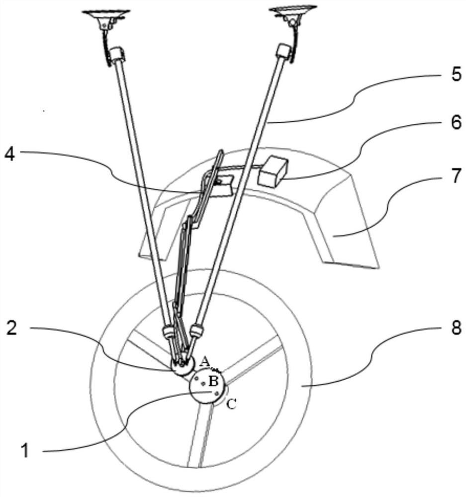
As shown 1 and 2, in the embodiment of the present invention, there is provided a non-contact on-line corner measuring system, comprising a mark 1, a light supplementing lamp 2, CMOS a camera 3, and an image processor 6. Wherein.
The markers 1 are three reflective marking points 8, A, B, positioned on the component to be measured C, such as an automobile steering component, including a steering wheel, a wheel, and the like, A, B centered on the same straight line and adjacent two adjacent dots unequal (e.g. C AB _AOMARKENCODTX0AO_INDELTA). BC). In one embodiment, three reflecting marking points A, B, C are arranged on the sticker, and the three reflecting marking points A, B and C are all round dots with the same shape. The sticker is fixed on the component to be tested 8 in a sticking manner.
The light supplementing lamp 2 is installed and fixed above the three reflecting mark points 5, A and B through the bracket C. The light supplementing lamp 2 is an infrared lamp bead which is annularly distributed, and a circular hole is reserved between the infrared light beads for mounting CMOS the camera 3.
CMOS Camera 3 is aligned with three reflective marking points A, B, C and is connected to image processor 4 via data line 6. The CMOS camera 3 is installed in a circular hole reserved in the light supplementing lamp 2, so that the peripheral circumference of the infrared light lamp bead ring 2 camera CMOS of the light supplementing lamp 3 is uniformly distributed, and CMOS cameras 3 and the light supplementing lamp 2 are arranged above the three reflecting mark points 5, A and B through the bracket C A. B The C utility model is suitable for a light filling lamp. At this time, CMOS camera 3 receives light filling lamp 2 and carries out image shooting with the infrared light of wavelength, and its optical axis coincides with light filling lamp 2's center line.
The image processor 6 is mounted on the table 7, which includes the following.
Image capture module 61 is used for gathering CMOS camera 3 shot's light filling lamp 2 and shines the facula image on three reflection mark points A, B, C.
, The three reflecting mark points 2 are illuminated by the light supplementing lamp A. B, C Of reflected light is captured by CMOS camera 3 and captured as a spot image, and CMOS camera 3 transmits each frame image through data line 4 to image acquisition module 6 in image processor 61.
The marker point area identification module 62 is used for binarizing the collected light spot image, and in the light spot image after binarization processing, three communication areas with three reflecting marking points A, B and C facula caving are identified.
, The marker-point area recognition module 62 performs binarization processing on the acquired light spot image, so that the value of the pixel point in the binarized spot image is 0 or 1.
The binarized processed light spot image is subjected to eight communication area search, the eight communication areas of all pixel points in the light spot image after the binarization processing are obtained, and three reflection mark points A are identified according to the preset connected area area range. B, C Facula racetrack's three communication areas.
It should be noted that binarization processing of a light spot image in the mark point area identification module 62, an eight communication area search, and the like belong to common technical means in the art, and detailed description thereof will not be repeated here.
The mark point position determination module 63 is configured to calculate a distance between the centers of gravity of the three communication areas Y1, Y2 and Y3, and determine a correspondence relationship between the center of gravity of the two communication areas according to the calculated distance between the centers of gravity of the two communication areas, A and B C and the three communication areas Y1, Y2 and Y3.
, The marker point position determination module 63 sets the identifiers of the three communication areas as Y1, Y2 and Y3 and calculates the center of gravity of the three communication areas Y1, Y2 and Y3 respectively, namely, the coordinates of the three reflection mark points A, B and C in the image. The distance between the center of gravity of the communication area Y1 and the center of gravity of the communication area Y2 is calculated as d12, and the distance between the center of gravity of the communication area Y2 Y1 and the center of gravity of the communication area Y3 Y3 d13 is d23 and.
If d12 > d23 > d13, the reflection mark point corresponding to the communication area Y3 is the middle point B of the three reflection mark points, the reflection mark point corresponding to the communication area Y1 is the reflection mark point A closest to the middle point distance among the three reflection mark points, and the reflection mark point corresponding to the communication area Y2 is the reflection mark point C farthest from the middle point. That is Y1 - _AOMARKENCODEGTX0AOA A, Y2 - _AOMARKENCODEGTX0AOA C, Y3 - _AOMARKENCODEGTX0AOA B.
If d12 > d13 > d23, the reflection mark point corresponding to the communication area Y3 is the middle point B of the three reflection mark points, the reflection mark point corresponding to the communication area Y1 is the reflection mark point C farthest from the middle point among the three reflection mark points, and the reflection mark point corresponding to the communication area Y2 is the reflection mark point A nearest to the middle point in the three reflection mark points. That is Y1 - _AOMARKENCODEGTX0AOA C, Y2 - _AOMARKENCODEGTX0AOA A, Y3 - _AOMARKENCODEGTX0AOA B.
If d13 > d23 > d12, the reflection mark point corresponding to the communication area Y2 is the middle point B of the three reflection mark points, the reflection mark point corresponding to the communication area Y1 is the reflection mark point A closest to the middle point distance among the three reflection mark points, and the reflection mark point corresponding to the communication area Y3 is the reflection mark point C farthest from the middle point. That is Y1 - _AOMARKENCODEGTX0AOA A, Y2 - _AOMARKENCODEGTX0AOA B, Y3 - _AOMARKENCODEGTX0AOA C.
If d13 > d12 > d23, the reflection mark point corresponding to the communication area Y2 is the middle point B of the three reflection mark points, the reflection mark point corresponding to the communication area Y1 is the reflection mark point C farthest from the middle point among the three reflection mark points, and the reflection mark point corresponding to the communication area Y3 is the reflection mark point A nearest to the middle point in the three reflection mark points. That is Y1 - _AOMARKENCODEGTX0AOA C, Y2 - _AOMARKENCODEGTX0AOA B, Y3 - _AOMARKENCODEGTX0AOA A.
If d23 > d12 > d13, the reflection mark point corresponding to the communication area Y1 is the middle point B of the three reflection mark points, the reflection mark point corresponding to the communication area Y3 is the reflection mark point A closest to the middle point distance among the three reflection mark points, and the reflection mark point corresponding to the communication area Y2 is the reflection mark point C farthest from the middle point. That is Y1 - _AOMARKENCODEGTX0AOA B, Y2 - _AOMARKENCODEGTX0AOA A, Y3 - _AOMARKENCODEGTX0AOA C.
If d23 > d13 > d12, the reflection mark point corresponding to the communication area Y1 is the middle point B of the three reflection mark points, the reflection mark point corresponding to the communication area Y3 is the reflection mark point C farthest from the middle point among the three reflection mark points, and the reflection mark point corresponding to the communication area Y2 is the reflection mark point A nearest to the middle point in the three reflection mark points. That is Y1 - _AOMARKENCODEGTX0AOA B, Y2 - _AOMARKENCODEGTX0AOA A, Y3 - _AOMARKENCODEGTX0AOA C.
The rotation angle calculation module 64 is used for calculating the rotation angle size of the component to be measured according to the correspondence relationship between the three reflection mark points A, B, C and the three communication areas Y1, Y2 and Y3.
, The turning angle calculating module 64 determines the coordinates of the center of gravity of each of the three reflecting markers A, B, C from the middle point B furthest and the nearest two reflecting marking points C, A respectively.
The slope of the determined two reflection mark points in the rectangular coordinate system is determined according to the determined slope of the communication area, and the angle value is obtained by using a triangle formula (such as an arctangent function formula) and the included angle of 8 connecting lines and a picture horizontal axis (AC axis in a rectangular coordinate system) is obtained by using the coordinates AC and the coordinates of the two points of the angle value of the detected part X to be measured. θ.
It is to be understood that since CMOS cameras 3 each photograph one frame image through data line 4 to image processor 6, if image processor 6 obtains a continuous frame image captured CMOS camera 3, three reflective marker points A may be generated in a continuous frame image. B, C'S position change relation, determine to await measuring part 8 one-way rotation's number of turns, consequently if part 8 that awaits measuring more than 360°, also can accurately calculate the multiturn angle.
As shown 3, in an embodiment of the present invention, a non-contact on-line rotation angle measurement method is provided, which is implemented in the aforementioned non-contact on-line rotation angle measurement system.
Step S1, the image processor acquires CMOS camera shooting's light filling lamp shines the facula image on the three reflection mark points.
The specific process is that the image processor acquires CMOS a light spot image formed on the three reflection mark points A, B and C photographed by the image processor, and CMOS camera transmits a frame image to the image processor storage through the data line.
Step S2, the image processor performs binarization processing on the acquired light spot image, and identifies three communication areas with three reflective marking point facula raceways in the binarized spot image.
, Firstly, the acquired light spot image is binarized, so that the value of the pixel point in the light spot image after binarization is 0 or 1.
Next, an eight communication area search is performed on the binarized light spot image to obtain the eight communication areas of all pixel points in the binarized light spot image, and three communication areas with three reflection mark dot light spots are identified according to the preset communication area area range.
Step S3. The image processor calculates the center of gravity of the three communication areas and obtains the distance between the centers of gravity of the two communication areas according to the calculated center of gravity of each communication area, and determines the correspondence between the three reflection mark points and the three communication areas according to the calculated distance between the center of gravity of the two communication areas.
, A distance between the center of gravity of the communication area Y1 and the center of gravity of the communication area Y2 is Y3, the distance between the center of gravity of the communication area Y1 and the center of gravity of the communication area Y2 is d12 d23 and, and the distance between the centers of gravity of Y1 Y2 communication d13 Y3 area Y3 and the center of gravity of the communication area.
d12 > d23 > d13, the reflection mark point corresponding to the communication area Y3 is the middle point of the three reflection mark points, the reflection mark point corresponding to the communication area Y1 is the reflection mark point closest to the middle point among the three reflection mark points, and the reflection mark point corresponding to the communication area Y2 is the reflection mark point farthest from the middle point in the three reflection mark points.
d12 > d13 > d23, the reflection mark point corresponding to the communication area Y3 is the middle point of the three reflection mark points, the reflection mark point corresponding to the communication area Y1 is the reflection mark point farthest from the middle point among the three reflection mark points, and the reflection mark point corresponding to the communication area Y2 is the reflection mark point closest to the middle point in the three reflection mark points.
d13 > d23 > d12, the reflection mark point corresponding to the communication area Y2 is the middle point of the three reflection mark points, the reflection mark point corresponding to the communication area Y1 is the reflection mark point closest to the middle point among the three reflection mark points, and the reflection mark point corresponding to the communication area Y3 is the reflection mark point farthest from the middle point in the three reflection mark points.
d13 > d12 > d23, the reflection mark point corresponding to the communication area Y2 is the middle point of the three reflection mark points, the reflection mark point corresponding to the communication area Y1 is the reflection mark point farthest from the middle point among the three reflection mark points, and the reflection mark point corresponding to the communication area Y3 is the reflection mark point closest to the middle point in the three reflection mark points.
d23 > d12 > d13, the reflection mark point corresponding to the communication area Y1 is the middle point of the three reflection mark points, the reflection mark point corresponding to the communication area Y3 is the reflection mark point closest to the middle point among the three reflection mark points, and the reflection mark point corresponding to the communication area Y2 is the reflection mark point farthest from the middle point in the three reflection mark points.
d23 > d13 > d12, the reflection mark point corresponding to the communication area Y1 is the middle point of the three reflection mark points, and the reflection mark point corresponding to the communication area Y3 is the reflection mark point farthest from the middle point among the three reflection mark points, and the reflection mark point corresponding to the communication area Y2 is the reflection mark point closest to the middle point in the three reflection mark points.
Step S4. The image processor calculates the corner size of the component to be measured according to the correspondence relationship between the three reflection mark points and the three communication areas.
, Firstly, the coordinates of the center of gravity of the communication area corresponding to the shortest distance from the middle point and the nearest two reflection mark points in the three reflection mark points are determined.
Next, the slope of the determined two reflection mark points in the rectangular coordinate system is determined according to the determined coordinates of the center of gravity of the communication area, and further according to the determined slope, the angle value is obtained by using the trigonometric equation and is recorded as the corner size of the component to be detected.
The embodiment of the invention has the following beneficial effects:
1, The CMOS camera is used for shooting the reflection mark points pasted on the part to be measured, and the specific processing algorithm is used for determining the corresponding angle size by using the specific processing algorithm.
2, Due to the fact that line segments on the same straight line are still on the same straight line in affine transformation and are not changed in proportion, even CMOS camera mounting positions cannot be directly facing to the mark paster, the requirement on CMOS camera installation positions is reduced, and the robustness of the measurement system is improved.
Those of ordinary skill in the art will appreciate that implementing all or part of the steps in the above-described embodiment methods may be accomplished by program instructions that may be stored in a computer-readable storage medium, such as ROM/RAM, a magnetic disk, an optical disk, or the like.
It is to be understood that both the foregoing general description and the following detailed description are exemplary and explanatory and are intended to provide further explanation of the invention as claimed.


 400-4929-0909
 contact@catarc.com.cn

