Contents of the invention
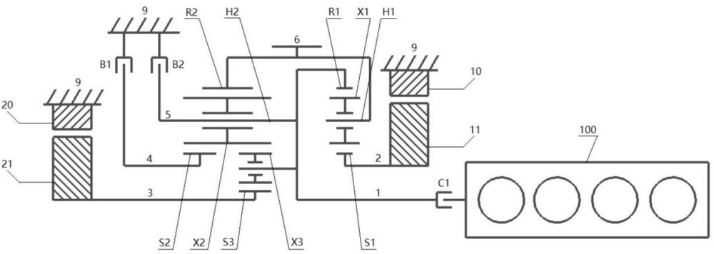
Aiming at the different scenarios of automobile use need to adapt to different working conditions, and the current mainstream hybrid power system is mostly single gear, and utilizing shift fork shift shift shift can produce power interruption or shift impact, will affect driving comfort and other problems, the first aspect of the present invention proposes a planetary gear hybrid system comprising: engine 100, the first motor M1, the second motor M2, the first planetary row, the second planetary row, clutch, brake and the structural element arranged between planetary rows for transmitting power;
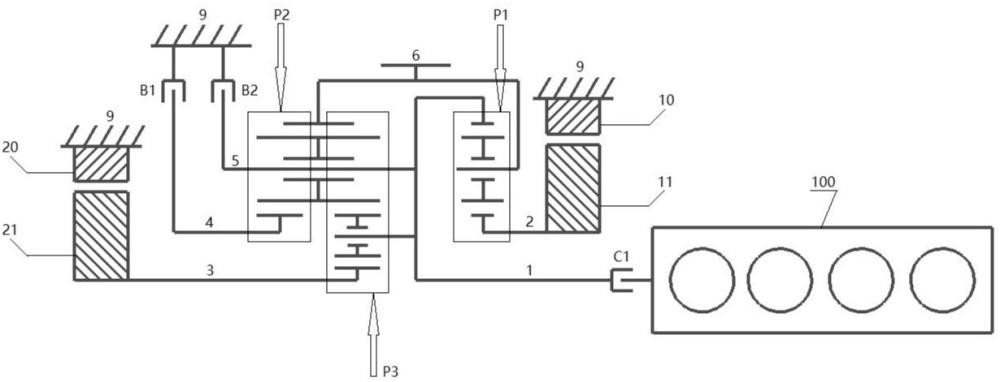
Described first planetary row is planetary row P1 comprises first sun gear S1, first planetary carrier H1, first gear ring R1; the second planetary row is made up of a planetary row P2 and a planetary row P3, and the second planetary row comprises a second sun gear S2, a third sun gear S3, a second planetary carrier H2, a second gear ring R2;
the clutch is a clutch C1, the brake comprises a first brake B1 and a second brake B2, the first motor M1 comprises a stator 10 and a rotor 11, and the second motor M2 comprises a stator 20 and a rotor 21;
Described structural element comprises shell 9, first structural element 1, second structural element 2, 3rd structural element 3, 4th structural element 4, 5th structural element 5, 6th structural element 6;
Described first structural element 1 is connected with the first gear ring R1 and the second planetary carrier H2, and is also connected with clutch C1; The other end of described clutch C1 is connected with the power take-off shaft of engine 100, and of course shock absorbing disc can also be arranged between clutch C1 and engine 100; Described second structural element 2 is connected to the first sun gear S1 at one end, and the rotor 11 of the first motor M1 is connected to the other end at the other end; Described third structural element 3 is connected to the third sun gear S3 at one end, and the rotor 21 of the second motor M2 is connected to the other end at the other end; Described fourth structural element 4 one end is connected with the second sun gear S2, and the other end is connected with the first brake B1; Described fifth structural element 5 one end is connected with the second planetary carrier H2, and the other end is connected with the second brake B2; One end of the sixth structural element 6 is connected with the first planetary carrier H1, and the other end is connected with the second gear ring R2.
Further, each planetary row is completely symmetrical with respect to the center of rotation, the power take-off shaft of the engine 100, the first motor M1 and the second motor M2 are installed on the same axis, and the stator 10 of the first motor M1 and the stator 20 of the second motor M2 are fixedly connected with the housing 9.
Further, the second planetary row further comprises a planetary gear X2 and a planetary gear X3, the planetary gear X2 and the planetary gear X3 are installed on the same planetary carrier, the planetary gear X2 is meshed with the planetary gear X3, the second sun gear S2 and the second gear ring R2 respectively, and the planetary gear X3 is meshed with the planetary gear X2 and the third sun gear S3 respectively;
Described planet row P2 and planet row P3 share the same planetary shelf, that is, the second planetary rack H2 is the planetary carrier of composite planetary row; The planetary row P2 and the planetary row P3 share the same gear ring, that is, the second gear ring R2 is used as the gear ring of the composite planetary row;
Described first brake B1 one end is connected with housing 9, and the other end is connected with the fourth structural element 4; Described second brake B2 one end is connected with housing 9, and the other end is connected with the fifth structural element 5.
Further, the second structural element 2 is designed as a hollow shaft for the first structural element 1 to pass through; It is understandable that the structural design further improves the overall compactness of the system through a reasonable layout.
Further, the planetary gears X1 are usually arranged in multiple circumferentially along the first sun gear S1; The planetary gear X2 and the planetary gear X3 are evenly distributed in multiple directions along the circumferential direction of the second sun gear S2 and the third sun gear S3 respectively.
Further, the first motor M1 and the second motor M2 are connected with the controller; The hybrid system further comprises a battery, a motor driver, etc., and the battery is connected with the motor driver, the first motor M1 and the second motor M2, and this part is the same as the existing dual-motor hybrid system.
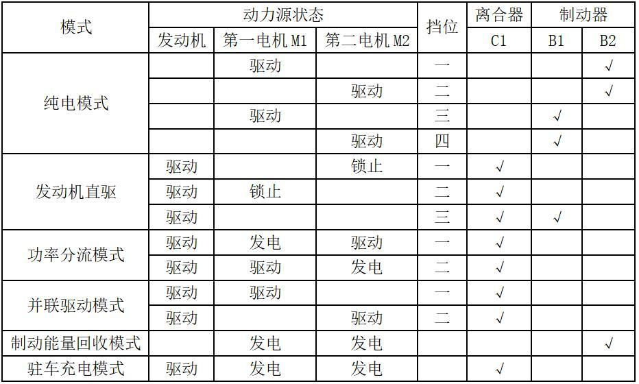
the second aspect of the application discloses a control method for a planetary gear hybrid power system, and the control method is used for controlling the hybrid power system; Wherein described control method controls the working state of engine 100, clutch C1, brake B1, brake B2, the first motor M1 and the second motor M2, can make described hybrid system switch to pure electric mode, engine direct drive mode, power shunt mode, parallel drive mode, braking energy recovery mode, parking charging mode.
Further, the hybrid system is controlled to switch to a pure electric drive mode, and the method comprises: the engine 100 stops working,
In conjunction with the second brake B2, the first motor M1 drives, and the second motor M2 does not work, and the hybrid system has a pure electric first gear;
In conjunction with the second brake B2, the first motor M1 does not work, and the second motor M2 drives, and the hybrid system has a pure electric second gear;
Combined with the first brake B1, the first motor M1 drives, and the second motor M2 does not work, and the hybrid system has pure electric three gears;
In conjunction with the first brake B1, the first motor M1 does not work, and the second motor M2 drives, and the hybrid system has a pure electric four gears.
Further, the hybrid system is controlled to switch to the engine direct drive mode, and the method comprises: the engine 100 starts work,
Combined with clutch C1, the third sun gear S3 rpm is zero by controlling the speed of the second motor M2 to be zero, and the hybrid system has an engine direct drive first gear;
Combined with clutch C1, the first sun gear S1 revolution is zero by controlling the speed of the first motor M1 to be zero, and the hybrid system has an engine direct drive second gear
Combined with clutch C1, first brake B1, the power output of engine 100 is transmitted to described sixth structural element 6 through described second planetary row, and described hybrid system has engine direct drive three gears.
Further, the hybrid system is controlled to switch to a power shunt mode, and the method comprises: the engine 100 starts to work, combined with the clutch C1, and the power output of the engine 100 is transmitted to the first gear ring R1 and the second planetary carrier H2, and the first motor M1 can be controlled to generate electricity, and the second motor M2 is driven; Or control the second motor M2 to generate electricity, and the first motor M1 drives.
Further, the hybrid system is switched to parallel drive mode, and the method comprises: engine 100 starting work
Described clutch C1 is combined, and the first motor M1 drives, and the second motor M2 does not work, and described hybrid system has parallel drive first gear;
Described clutch C1 is combined, the first motor M1 does not work, and the second motor M2 drives, and the hybrid system has parallel drive two gears.
Further, the hybrid system is controlled to switch to the braking energy recovery mode, the method comprises: the engine 100 stops working, combined with the second brake B2, the rotating torque is transmitted to the first planetary carrier H1 and the second gear ring R2 through the sixth structural element 6, the first sun gear S1 and the third sun gear S3 rotate, and the first motor M1 and the second motor M2 both rotate to generate electricity.
Further, the hybrid system is controlled to switch to the parking charging mode, the method comprises: it can be understood that the 6 revolutions of the sixth structural element are zero when parking, the engine 100 starts to work, combined with the clutch C1, the power output of the engine 100 is transmitted to the first gear ring R1 and the second planetary carrier H2, the first sun gear S1 and the third sun gear S3 rotate, and the first motor M1 and the second motor M2 both rotate to generate electricity.
In the above-mentioned technical scheme, the planetary gear hybrid system provided by the present invention and its control method have the following beneficial effects:
1. The planetary gear hybrid system proposed by the present invention and its control method, this planetary gear hybrid system adopts planetary gear set transmission, realizes by changing the working state of the planetary row when switching the working state, reduces the use of brake and clutch, realizes that the shift operation can adapt to different vehicle use scenarios, and the power transmission performance is superior; Compared with the shift fork, the structure is compact, the degree of integration is higher, the comfort of shifting is good, it has a larger torque capacity, the shift logic is clear, the control is simple, it can effectively avoid the problem of shifting gear, and there is no need to set up a set of shift control mechanism for specially manipulating the shift fork.
2. This planetary gear hybrid system adopts the structure of dual motors, which can use the motor to achieve drive or power generation, and the motor power utilization rate is high, the acceleration performance is good, and the layout of the transmission device is optimized. And according to the demand, the engine and motor can be driven separately or at the same time, and the engine can be directly driven, pure electric, power shunt or parallel drive operation, improve the flexibility of power source selection, improve the output power in the hybrid drive state, and meet the power demand.
3. Through the control of the planetary gear set or motor, the planetary gear hybrid system realizes the shift of the engine when it is directly driven, so that the engine can be kept in the working condition of better fuel economy and reduce the operating fuel consumption of the engine at a relatively high speed.
The specific embodiment
The following is combined with the embodiments of the present invention and the accompanying drawings, and the technical solutions in the embodiments of the present invention are clearly and completely described. The illustrations provided in the following embodiments illustrate the basic ideas of the present invention only in a schematic manner, and without conflict, the following embodiments and the features in the embodiments may be combined with each other. In order to better illustrate the embodiments of the present invention, some parts of the drawings will be omitted, enlarged or reduced, and do not represent the dimensions of the actual product. In the present invention, the terms "first", "second", "third", are used for descriptive purposes only and should not be construed as indicating or implying relative importance; The term "multiple" means two or more of them; Words such as "settings" and "connections" shall be construed broadly unless expressly defined otherwise. It is understandable that certain well-known structures in the drawings and their descriptions may be omitted for those skilled in the art and cannot be construed as a limitation on the present invention, and for those skilled in the art, the specific meaning of the above terms can be understood according to the specific circumstances.
The housing 9 described in this article is stationary at all times, and the first motor M1 comprises a stator 10 and a rotor 11, and the second motor M2 comprises a stator 20 and a rotor 21; In the engine direct drive mode, the first motor M1 and the second motor M2 are locked in state, that is, the motor rotor number is zero, and the control motor number is zero, which belongs to the well-known technology in the field of electrical control engineering, is not the focus of the present invention, and will not be introduced below; The planetary rows of this hybrid system are perfectly symmetrical with respect to the center of rotation, and the lower half of the center of rotation is omitted in Figures 1 and 2 and will not be described below.
Examples:
Referring to Table 1, Fig. 1 and Fig. 2, a planetary gear hybrid system according to the first embodiment of the present invention comprises: engine 100, a first motor M1, a second motor M2, a first planetary row, a second planetary row, a clutch, a brake and a structural element arranged between planetary rows for transmitting power; Described first planetary row is planetary row P1 comprises first sun gear S1, first planetary carrier H1, first gear ring R1; the second planetary row is formed by combining a star row P2 and a planetary row P3, and the second planetary row comprises a second sun gear S2, a third sun wheel S3, a second planetary carrier H2, and a second gear ring R2;
the clutch is a clutch C1, the brake comprises a first brake B1 and a second brake B2, the first motor M1 comprises a stator 10 and a rotor 11, and the second motor M2 comprises a stator 20 and a rotor 21; Described structural element comprises shell 9, first structural element 1, second structural element 2, 3rd structural element 3, 4th structural element 4, 5th structural element 5, 6th structural element 6;
the first structural element 1 connects the first gear ring R1 and the second planetary carrier H2, and is also connected with the clutch C1, which can be understood as the first gear ring R1 and the second planetary carrier H2 are fixedly connected; The other end of described clutch C1 is connected with the power take-off shaft of engine 100. Described second structural element 2 is connected to the first sun gear S1 at one end, and the rotor 11 of the first motor M1 is connected to the other end at the other end, which can be understood as the rotor 11 of the first motor M1 is fixedly connected with the first sun gear S1; Described third structural element 3 is connected to the third sun gear S3 at one end, and the rotor 21 of the second motor M2 is connected to the other end at the other end, which can be understood as the rotor 21 of the second motor M2 is fixedly connected with the third sun gear S3; Described fourth structural element 4 one end is connected with the second sun gear S2, and the other end is connected with the first brake B1; Described fifth structural element 5 one end is connected with the second planetary carrier H2, and the other end is connected with the second brake B2; Described sixth structural element 6 is connected to the first planetary carrier H1 at one end, and the other end is connected with the second gear ring R2, which can be understood as the first planetary carrier H1 and the second gear ring R2 are fixedly connected.
The planetary gear hybrid system of the present invention can realize a plurality of power modes, mainly comprising pure electric mode, engine direct drive mode, power shunt mode, parallel drive mode, braking energy recovery mode and parking charging mode, and the power mode is as follows:
Refer to Table 1, Figure 1 and Figure 2, it can be understood that the engine 100 does not work under the various gears of pure electric drive, and the clutch C1 disconnects to prevent the engine 100 from being dragged backwards.
Pure electric first gear: combined with the second brake B2, the first motor M1 drive
Combined with the second brake B2, the second planetary carrier H2 is fixedly connected with the housing 9, the second planetary carrier H2, the first structural element 1, the first gear ring R1 rotation speed is zero, the first motor M1 drives, and the first sun gear S1 and the first motor M1 rotate at the same speed; The first motor M1 transmits power to the second structural element 2, the first sun gear S1, the first planetary carrier H1, and the sixth structural element 6 to output power externally.
Pure electric second gear: combined with the second brake B2 and the second motor M2 drive
Combining the second brake B2, the second planetary carrier H2 is fixedly connected with the housing 9, the second planetary carrier H2 rotation speed is zero, the second motor M2 drives, and the third sun gear S3 rotation speed is the same as the second motor M2 rotational speed; The second motor M2 transmits power to the third structural element 3, the third sun gear S3, planetary gear X3, planetary gear X2, the second gear ring R2, and the sixth structural element 6 to output power externally.
Pure electric three gears: combined with the first brake B1 and the first motor M1 drive
Combined with the first brake B1, the second sun gear S2 is fixedly connected with the housing 9, and the second sun gear S2 rotation speed is zero; The first motor M1 drives, the first sun gear S1 and the first motor M1 have the same number of revolutions, and the first motor M1 transmits power to the second structural element 2, the first sun gear S1, the planetary gear X1, the first gear ring R1, the first structural element 1, the second planetary carrier H2, the second ring gear R2, and the sixth structural element 6 output power externally.
Pure electric four gears: combined with the first brake B1, the second motor M2 drive
Combined with brake B1, the second sun gear S2 is fixedly connected with the housing 9, and the second sun gear S2 rotation speed is zero; the second motor M2 drives, and the second motor M2 is the same as the third sun gear S3 revolution; The second motor M2 transmits power to the third structural element 3, the third sun gear S3, the planetary gear X3, the planetary gear X2 in turn, and the third sun gear S3, the planetary gear X3 and the planetary gear X2 transmit the power to the second gear ring R2 through the common planetary carrier H2, and the sixth structural element 6 outputs power externally.
Engine direct drive first gear: combined with the clutch C1, control the second motor M2 speed is zero
Combined with clutch C1, the second planetary carrier H2 is connected with engine 100 power and the number of revolutions is the same, the speed of the control second motor M2 is zero, and the number of revolutions of the third sun gear S3 and the second motor M2 is the same and is zero; The engine 100 transmits power to clutch C1, the first structural element 1, the second planetary carrier H2, the second ring gear R2, the sixth structural element 6 to output power externally.
Engine direct drive second gear: combined with the clutch C1, control the first motor M1 speed is zero
Combined with clutch C1, the first gear ring R1 is connected with the engine 100 power and the number of revolutions is the same, the speed of the control first motor M1 is zero, and the number of revolutions of the first sun gear S1 and the first motor M1 is the same and are zero; The engine 100 transmits power to clutch C1, the first structural element 1, the first gear ring R1, the first planetary carrier H1, the sixth structural element 6 to output power externally.
Engine direct drive three gears: combined with clutch C1, the first brake B1
Combined with the first brake B1, the second sun gear S2 is fixedly connected with the housing 9, and the second sun gear S2 revolutions are zero; Combined with clutch C1, the first structural element 1 is connected with the engine 100 power and the number of revolutions is the same; The engine 100 transmits power to clutch C1, the first structural element 1, the second planetary carrier H2, the planetary gear X2, the second ring gear R2, the sixth structural element 6 to output power externally.
Power split mode: Combined with clutch C1
Combine clutch C1 first gear ring R1 and second planet carrier H2 and engine 100 power communication and the same number of revolutions, and engine 100 transmits power to clutch C1, first structural element 1, first gear ring R1 and second planet carrier H2; The engine 100 can drive the first motor M1 to rotate, and the first motor M1 generates electricity as a generating motor, and the second motor M2 works as a driving motor; Or the engine 100 drives the second motor M2 to rotate, and the second motor M2 generates electricity as a generating motor, and the first motor M1 works as a driving motor. In this mode, according to the output power demand of the vehicle, the engine 100, the first motor M1, the second motor M2 and the first planetary row or the second planetary row work together to ensure that the engine is always in the high-efficiency working range, so as to ensure fuel economy, improve the comprehensive power and economy of the whole vehicle; The engine can have good fuel economy, which is conducive to reducing the use of batteries and improving battery life, thereby improving the comprehensive economy of the whole vehicle.
Parallel drive mode 1st gear: combined with clutch C1, the first motor M1 drive
Combine clutch C1 first gear ring R1 and engine 100 power connection and the number of revolutions is the same, engine 100 transmits power to clutch C1, first structural element 1, first gear ring R1; At the same time, the first motor M1 is driven, and the power is transmitted to the second structural element 2 and the first sun gear S1; The two forces converge on the first planetary carrier H1 and then transmit to the sixth structural element 6 to output power externally.
Parallel drive mode 2nd gear: combined with clutch C1, the second motor M2 drive
Combine clutch C1 second planetary carrier H2 and engine 100 power communication and the same number of revolutions, and engine 100 transmits power to clutch C1, first structural element 1, second planetary carrier H2; At the same time, the second motor M2 drives, transmits power to the third structural element 3, the third sun gear S3, and the two strands of power converge on the second planetary carrier H2, and then transmits to the second gear ring R2, and the sixth structural element 6 outputs power externally.
Regenerative braking mode:
When vehicle braking in described various modes, described engine 100 does not work, and described clutch C1 disconnects to prevent engine 100 from being dragged backwards; the second brake B2 is combined, the second planetary carrier H2, the first structural element 1 and the first gear ring R1 are zero, the first motor M1 and the second motor M2 are subjected to reverse torque rotation to generate electricity, and the hybrid system enters the braking energy recovery mode; At this moment, the braking energy recovery route is divided into two roads: one is the sixth structural element 6, the first planetary carrier H1, the planetary gear X1, the first sun gear S1, the second structural element 2, the first motor M1 rotates to generate electricity; The other way is, the sixth structural element 6, the second gear ring R2, the planetary gear X2, the planetary gear X3, the third structural element 3, the second motor M2 rotate to generate electricity, and this mode is applied to vehicle braking energy recovery.
Parking charging mode: engine 100 start work, combined with clutch C1
It is understandable that when entering the parking charging mode, the parking mechanism locks the wheel, and then the sixth structural element 6 revolutions are zero, combined with the clutch C1, the first gear ring R1 and the second planet carrier H2 are connected with the engine 100 power connection, and the number of revolutions is the same; The engine 100 transmits power to clutch C1 and the first structural element 1 in turn, and the power is divided into two ways and one way: one road is transmitted to the first gear ring R1, planetary gear X1, the first sun gear S1, the second structural element 2, and the first motor M1 generates electricity as a generator motor; The other channel is transmitted to the second planetary carrier H2, the planetary gear X2, the planetary gear X3, the third sun gear S3, the third structural element 3, and the second motor M2 is used as a power generating motor to generate electricity.
Reverse gear: the reverse gear has the following two implementation forms
1. Combined with brake B2, the first motor M1 is reversed and driven, and the power is successively transmitted to the second structural element 2, the first sun gear S1, the first planet carrier H1, and the sixth structural element 6 reverse external output power;
2. combined with brake B2, the second motor M2 reverse drive, and the power is successively transmitted to the third structural element 3, the third sun gear S3, the planetary gear X3, the planetary gear X2, the second gear ring R2, the sixth structural element 6 reverse external output power.
Of course, the adaptation relationship between gear and road conditions is not limited to the above situation, according to fuel consumption and power, different gear distribution modes can be arranged for different road conditions, and the adaptation relationship between gear and road conditions is not limited here.
Table 1 shows the gear control logic diagram of this planetary gear hybrid system
Table 1:
![]()
Note: "√" in the table means that the clutch or brake is combined, and no "√" means that it is not combined.
The embodiments described above are some embodiments of the present invention, but not all embodiments; Based on the embodiments in the present invention, all other embodiments obtained by a person skilled in the art without creative labor belong to the scope of protection of the present invention.








 400-4929-0909
 contact@catarc.com.cn