Summary of the utility model
In view of this, this utility model addresses the deficiencies of the prior art. Its main purpose is to provide a brake pedal device for automotive kinetic energy recovery control. By structurally improving the brake pedal assembly for existing mass-produced vehicles and integrating a high-precision, long-life brake pedal status sensor, it can accurately and real-time feedback on different stroke positions of the pedal, providing a solid and accurate physical signal foundation for the upper-layer controller to execute innovative kinetic energy recovery strategies.
To achieve the above purpose, the utility model adopts the following technical embodiments:
A brake pedal device for automotive kinetic energy recovery control, comprising:
Fixed bracket, fixed to the vehicle body;
The brake pedal arm can be rotatably mounted on the fixed bracket via the pedal shaft;
A brake pedal status sensor, installed on the fixed bracket, used to detect the rotational travel of the brake pedal arm relative to the fixed bracket;
The brake pedal status sensor is configured to output different electrical signals to the vehicle's VCU when the brake pedal arm reaches different travel positions, controlling the intensity of kinetic energy recovery.
As a preferred embodiment: the brake pedal status sensor is a Hall sensor assembly, including a Hall element fixed on the fixed bracket and a magnet mounted on the brake pedal arm or set with the brake pedal arm and corresponding to the Hall element.
As a preferred embodiment: the brake pedal status sensor includes a first mechanical switch and a second mechanical switch;
The first mechanical switch is set to be triggered when the brake pedal arm reaches the first preset travel position;
The second mechanical switch is set to be triggered when the brake pedal arm reaches the second preset travel position, and the second preset stroke is greater than the first preset stroke.
As a preferred embodiment: further comprising a third mechanical switch, the third mechanical switch is set to be triggered when the brake pedal arm reaches the third preset travel position, and the second preset stroke lies between the first preset stroke and the third preset stroke.
As a preferred embodiment: the first mechanical switch shares the same switch with the vehicle's brake light switch.
As a preferred embodiment: the first mechanical switch, second mechanical switch, and/or third mechanical switch are micro switches fixed vertically on the fixed bracket, and their trigger buttons are located along the movement path of the brake pedal arm.
As a preferred embodiment: the straight-line distance between the trigger button of the first mechanical switch and the second mechanical switch is 2-3 millimeters.
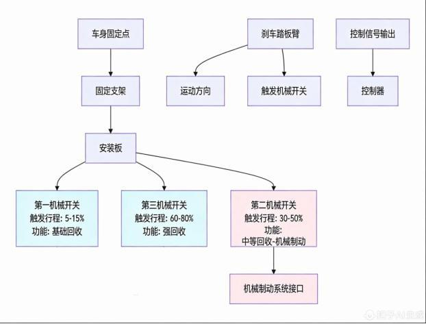
As a preferred embodiment: the first preset stroke is set to 5%-15% of the total brake pedal travel, the second preset stroke is set to 30%-50% of the total brake pedal travel, and the third preset stroke is set to 60%-80% of the total brake pedal travel.
As a preferred embodiment: the brake pedal status sensor includes a housing, gears installed in the housing, rack, first spring, trigger lever, turntable, Hall sensor, magnetic strip, and brake light trigger switch; The gear is fixedly connected to the turntable, and the Hall sensor is installed in the housing and is close to the edge of the turntable; The magnetic strips are distributed along the edge of the turntable, with their magnetic strength transitioning from weak to strong along the turntable's edge. The outer surface of the magnetic strip is opposed to the Hall sensor as the turntable rotates; The first spring is arranged laterally inside the housing, the trigger rod abuts the end of the first spring, its front end extends outside the housing, and it is detachably abutted with the brake pedal arm; The rack is connected to the rear end of the trigger rod. The brake light trigger switch includes a trigger button and a second spring. The second spring is installed on the lower inner side of the housing, with the rear end of the trigger button abutting against the second spring. The front end of the trigger button extends outside the housing. When the brake is not pressed, the trigger button elastically abuts against the brake pedal arm. The length of the trigger button extending out of the housing is shorter than the length of the trigger lever extending from the housing.
As a preferred embodiment: the Hall element can be slidably installed on the inner side wall of the fixed bracket along with the brake pedal, while the magnet is fixed to the fixed bracket. Its magnetic strength changes from weak to strong along the sliding start to end position of the Hall element; When the brake pedal is pressed, the brake pedal arm rotates and pushes the Hall element to slide along the lateral sliding groove, changing the relative position and air clearance between the magnet and the Hall element.
Compared with the prior art, this utility model has obvious advantages and beneficial effects. Specifically, from the above technical embodiments, first, the non-contact Hall sensor embodiment completely avoids mechanical wear, has a long lifespan, high reliability, and can output continuous signals to achieve smooth stepless control, thereby enhancing the vehicle's grade and user experience. Second, the provided multi-mechanical switch alternative embodiments have a simple structure, low cost, and are easy to implement and promote in production; In particular, by sharing the original brake light switch as the first-stage trigger switch, the structure and wiring are greatly simplified, reducing the cost and complexity of modification. Finally, precise mechanical design (such as setting a 2-3 mm switch spacing or corresponding stroke percentage) ensures accurate activation of all functions and clear foot-feel feedback, guaranteeing that control strategies are executed stably and consistently.
To more clearly explain the structural features and efficacy of this utility model, the following provides a detailed description in conjunction with the accompanying drawings and specific embodiments.
Specific embodiments
As shown in Figures 1 to 18, this utility model relates to a brake pedal device for automotive kinetic energy recovery control. It changes the existing electric vehicle mode of "releasing the accelerator pedal to activate strong kinetic energy recovery." By transferring the trigger and control of kinetic energy recovery to the brake pedal, it achieves optimal management of energy recovery and inertia coasting under different driving conditions, thereby effectively improving the vehicle's overall driving range.
The kinetic energy recovery control system of this utility model mainly includes the following parts:
Pedal status sensor 1: Used to monitor the driver's pedal operation in real time, converting it into different electrical signals that are transmitted to the vehicle's VCU (Vehicle Control Unit) to control the strength of kinetic energy recovery. Includes the accelerator pedal position sensor 11 (microswitch switch) and the brake pedal status sensor 12. The brake pedal status sensor 12 adopts the following two embodiments:
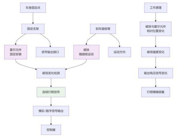
First embodiment (stepless adjustment): uses a Hall sensor assembly. The Hall sensor assembly includes a Hall element 121 fixed to a fixed bracket 134 fixed to the vehicle body, and a magnet 122 fixedly mounted on or operated with the brake pedal arm 15 and corresponding to the Hall element 121. When the brake pedal 14 is pressed, the brake pedal arm 15 rotates, changing the relative position of the magnet 122 and the Hall element 121, causing a change in the magnetic field. The Hall element 121 outputs an electrical signal proportional to the brake pedal 14 stroke and transmits it to the vehicle's controller VCU, which controls the strength of kinetic energy recovery.
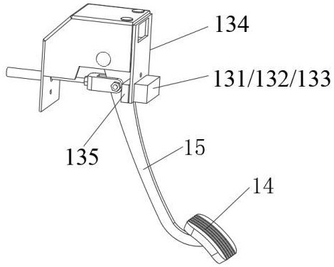
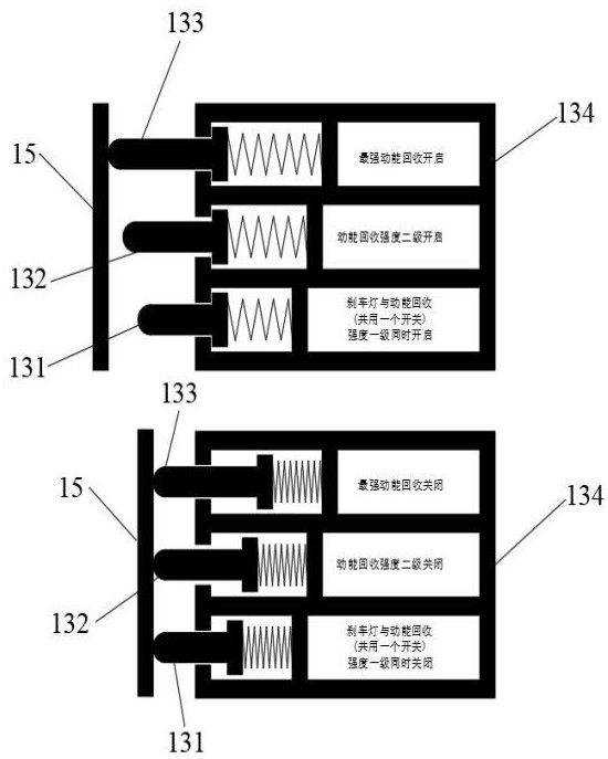
Second embodiment (multi-stage adjustment): Multiple mechanical switches 13 are used. Multiple mechanical switches 13 are installed vertically at intervals on the fixed bracket 134, and their trigger buttons are located along the movement path of the brake pedal arm 15. By setting the first mechanical switch 131, second mechanical switch 132, third mechanical switch 133, and their different trigger strokes (for example, by spacing the trigger buttons of adjacent switches by 2-3 millimeters), different mechanical switches can be triggered separately when the brake pedal arm 15 reaches different stroke positions, triggering different intensities of kinetic energy recovery and mechanical braking. The first mechanical switch 131 can share the same switch with the vehicle's original brake light trigger switch 58.
Controller 2 (automotive VCU): electrically connected to all brake pedal status sensors 12. Controller 2 contains pre-stored control logic to receive signals from the brake pedal status sensor 12, which then issues control commands to the actuators (automotive energy recovery system 3 and mechanical braking system 4).
The control method workflow is as follows:
The control logic executed by controller 2 is as follows:
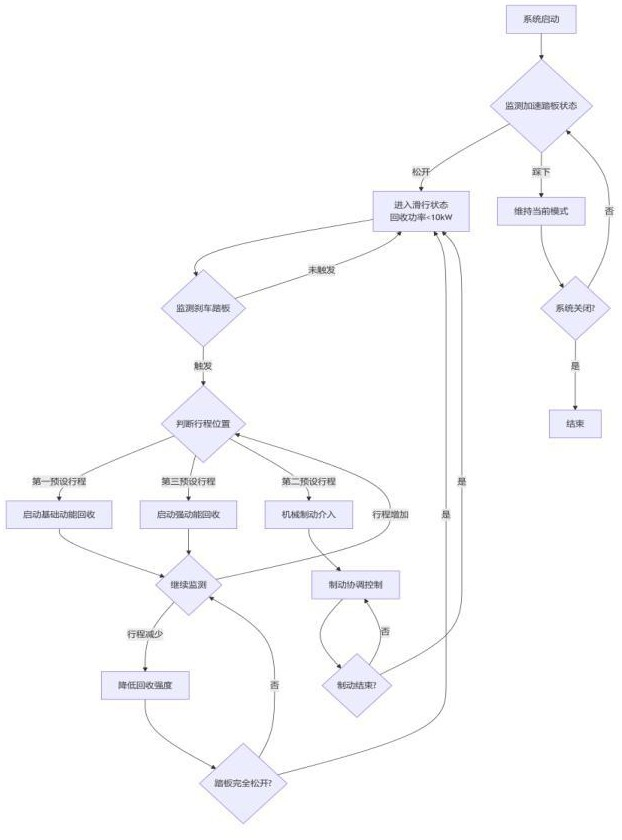
1. Coasting status determination and control: When controller 2 detects the accelerator pedal being released via the acceleration pedal position sensor 11, it immediately controls the vehicle's kinetic energy recovery system 3 to enter "coasting state." This "coasting state" is explicitly defined as the vehicle's kinetic energy recovery system not working, or energy recovery at a lower power below 10 kW. The purpose of this setting is to maximize the vehicle's inertial coasting distance and avoid unnecessary speed decay. Experimental verification shows that this strategy can improve driving range by 4%-7% compared to traditional strong recovery modes under highway and other smooth road conditions.
2. Kinetic energy recovery start and adjustment: When controller 2 detects that brake pedal 14 has been triggered through the brake pedal status sensor 12, the system enters the "on-demand recovery" phase.
In the first embodiment, the controller (VCU) 2 continuously adjusts the intensity of kinetic energy recovery on the brake pedal 14 within the range from the first preset stroke (e.g., corresponding to 5%-15% of the total pedal travel) to the second preset stroke (e.g., corresponding to 60%-80% of the total pedal travel) based on the continuous travel signal provided by the Hall sensor (Hall element). The recovery intensity is positively correlated with the pedal travel. To achieve precise control, controller 2 generates PWM (Pulse Width Modulation) signals to adjust the generation torque of the drive motor of the automotive energy recovery system 3.
In the second embodiment, when the brake pedal 14 reaches the first preset stroke (triggered by the first mechanical switch), kinetic energy recovery for the foundation strength is activated, and the brake light turns on; It should be noted that the first mechanical switch 131 may not be shared with the brake light trigger switch 58. That is, after the brake light trigger switch 58 is triggered, the first mechanical switch 131 is triggered as the brake pedal 14 continues to press down. When the brake pedal 14 is pressed again to reach the second preset stroke (triggered by the second mechanical switch 132), a stronger level of kinetic energy recovery is activated. The brake pedal 14 is further pressed down to reach the third preset stroke (triggered by the third mechanical switch 133), initiating the strongest first gear of kinetic energy recovery. The first preset stroke is set to 5%-15% of the total brake pedal travel, the second preset stroke is set to 30%-50% of the total brake pedal travel, and the third preset stroke is set to 60%-80% of the total brake pedal travel. The intervals between the first, second, and third preset strokes generally correspond to a section of idle travel or damping on the brake pedal 14 that is significantly smaller than the range when pressing the pedal deeply, providing the driver with clear control feedback.
3. Mechanical brake intervention: When greater deceleration is required, the brake pedal 14 is deeply pressed to the second preset stroke (triggered by the second mechanical switch 132 in the second embodiment); It can also be set so that when the brake pedal 14 is deeply pressed to the first preset stroke, the mechanical brake system 4 engages, specifically designed according to the actual braking system trigger of the vehicle. The controller (VCU) 2 will control the mechanical braking system 4 to intervene, providing braking force together or independently with the vehicle's kinetic energy recovery system 3 to ensure driving safety.
Through the above method, this utility model ensures that kinetic energy recovery is intelligently activated only when deceleration is needed, effectively balancing the contradiction between inertial coasting and energy recovery, and maximizing the efficiency of electrical energy use.
The best embodiment of this utility model is described in detail below in conjunction with the drawings. It should be noted that the following embodiments are only for explaining this utility model and are not intended to limit the scope of protection of this utility model.
Stepless adjustment solution based on Hall sensors:
Referring to the system block diagram shown in Figure 1, the kinetic energy recovery control system in this embodiment includes: pedal status sensor 1, controller 2, automotive kinetic energy recovery system 3, and mechanical brake system 4.
The fixing bracket 134 is fixed to the vehicle body, and the pedal status sensor 1 includes the acceleration pedal position sensor 11 and the brake pedal status sensor 12. The brake pedal status sensor 12 uses a Hall sensor assembly, including a Hall element 121 fixed on the fixed bracket 134, and a magnet 122 fixedly mounted on the brake pedal arm 15 or set with the movement of the brake pedal arm 15 and corresponding to the Hall element 121.
Controller 2 executes the following control logic:
Step S201: Real-time monitoring of the accelerator pedal status;
Step S202: When the accelerator pedal is detected to be released, control the vehicle's kinetic energy recovery system 3 to enter coasting mode, causing the energy recovery system to stop working or limit the recovery power to below 10 kW;
Step S203: Real-time monitoring of brake pedal travel;
Step S204: When the brake pedal travel exceeds the first preset stroke (e.g., 10% of the total pedal travel), the continuous stroke signal provided by the Hall sensor is used to steplessly adjust the kinetic energy recovery intensity via PWM;
Step S205: When the brake pedal travel exceeds the second preset stroke (such as 70% of the total pedal travel), control the mechanical brake system 4 to intervene.
Multi-level adjustment solution based on mechanical switches:
In this embodiment, three mechanical switches are arranged on the brake pedal assembly: the first mechanical switch 131, the second mechanical switch 132, and the third mechanical switch 133.
These switches are installed on the fixed bracket 134, with the trigger buttons of each switch located along the movement path of the brake pedal arm. The first mechanical switch 131, second mechanical switch 132, and third mechanical switch 133 correspond to different trigger strokes.
Controller 2 executes the following control logic:
Step S301: Real-time monitoring of accelerator pedal status;
Step S302: When the accelerator pedal is detected to be released, control the kinetic energy recovery system 3 to enter sliding mode;
Step S303: Real-time monitoring of the trigger status of each mechanical switch;
Step S304: When the first mechanical switch 131 is triggered, the brake light turns on, simultaneously initiating kinetic energy recovery for the foundation strength;
Step S305: When the second mechanical switch 132 is triggered, the mechanical braking system 4 is activated and activated, while a higher intensity of kinetic energy recovery is initiated;
Step S306: When the third mechanical switch 133 is triggered, initiates the highest intensity of kinetic energy recovery;
Technical Effect Verification:
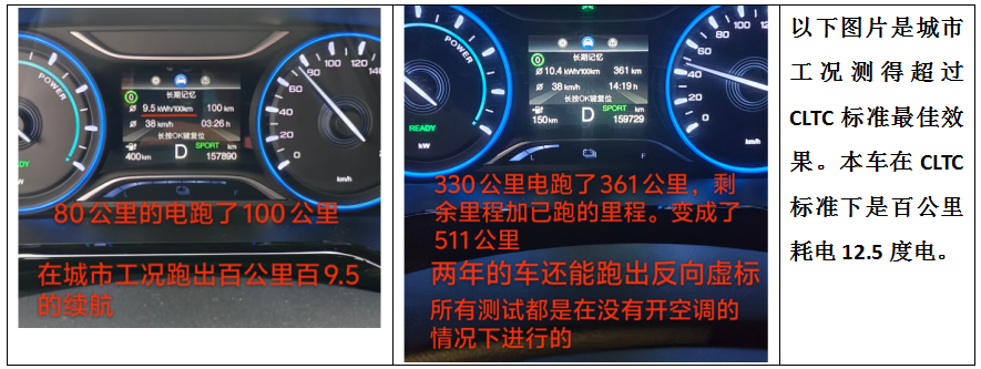
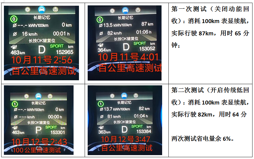
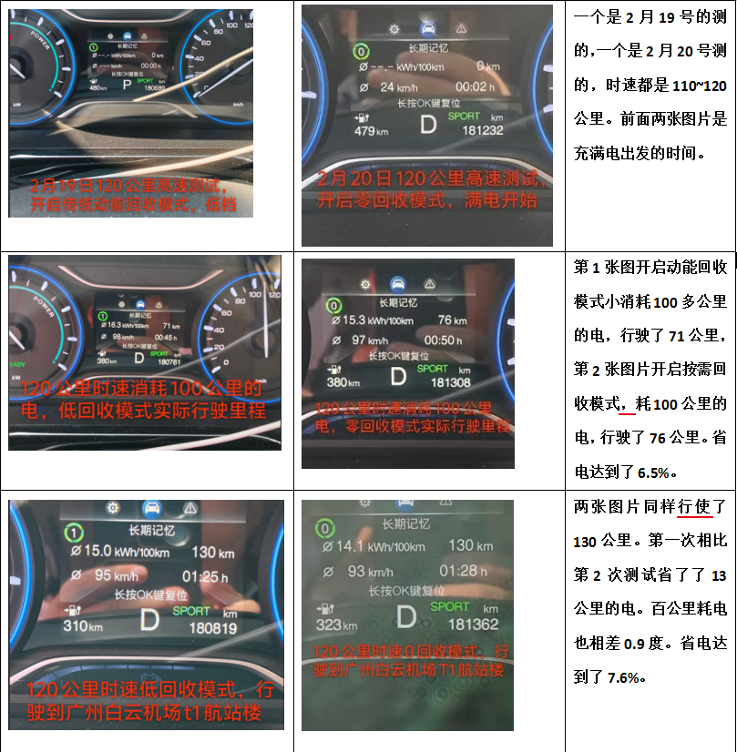
Using the traditional accelerator pedal-controlled kinetic energy recovery method, two nighttime highway tests were conducted. Test conditions: speed 80-105 km/h, air conditioning at 25°C at first setting, low beams on, outdoor temperature 26°C. The test results are as follows:
First test (with energy recovery off): 100km of displayed range, actual driving of 87km, 65 minutes;
Second test (with traditional low recovery enabled): 100 km of displayed range, actual driving of 82 km, 63 minutes;
After adopting the brake pedal control method of this utility model, long-term testing shows that under the same weather and road conditions, Compared to the traditional loose pedal recycling mode, the same model can deliver an average range extension of 4%-7%.
This indicates that compared to the traditional low recycling mode, this utility model can improve driving range by about 5%, and compared to turning off the recycling mode and using intelligent recycling strategies, it still achieves net energy gains.
The following explains each drawing:
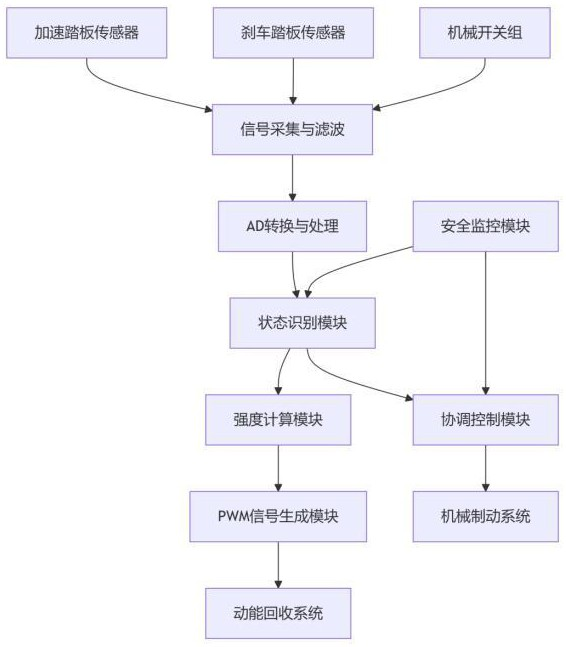
Figure 1 shows the overall system architecture flowchart, showing the interactions among hardware components. The pedal status sensor 1 shown in the figure is the system's perception starting point, i.e., real-time monitoring of the driver's operation of the accelerator pedal position sensor 11 and brake pedal status sensor 12. These sensing signals are transmitted to the system's decision-making hub—the Controller (VCU)2. Controller 2 calculates and judges based on pre-stored control logic, ultimately issuing commands to two execution terminals—the automotive kinetic energy recovery system 3 (drive motor) and the mechanical braking system 4 (such as ESP). This complete "perception-decision-execution" closed-loop architecture is the physical foundation for the core utility model concept of "transferring the trigger and control of kinetic energy recovery from the accelerator pedal to the brake pedal," ensuring that the entire process from driving intent to vehicle deceleration and energy recovery can be precisely and coordinatedly.
In the system architecture shown in Figure 1, multiple functional modules collaborate to achieve closed-loop control from driving intent sensing to energy recovery and braking execution. The system collects driver operations in real time through accelerator and brake pedal sensors, with the brake pedal sensor configurable as a mechanical switch group for multi-stage triggering. The collected analog signals are denoised and shaped by the signal acquisition and filtering module, then converted into digital signals by the AD conversion and processing module for use by subsequent control units. The safety monitoring module continuously monitors the status of all sensors and actuators to ensure the system operates within safe limits. After entering the control core, the status recognition module determines whether the vehicle is coasting or braking based on pedal signals; When it is recognized as braking, the strength calculation module calculates the corresponding energy recovery intensity based on the brake pedal stroke and transmits the result to the PWM signal generation module, generating PWM signals corresponding to the duty cycle to adjust the motor torque of the kinetic energy recovery system. The coordination control module coordinates the working sequence and force distribution between the energy recovery system and mechanical braking system at appropriate times according to braking needs and vehicle dynamics, ensuring a smooth, efficient, and responsive braking process that ultimately achieves precise matching between energy recovery and vehicle deceleration.
Figure 2 shows the main control flowchart: when the accelerator pedal is detected to be released, the vehicle's kinetic energy recovery system 3 is immediately controlled to enter "coasting mode," without initiating kinetic energy recovery or limiting the recovery power to below 10 kW. Its fundamental purpose is to address the inherent flaw pointed out in the background technology—avoiding interruption of inertial coasting due to unnecessary strong regenerative braking force in smooth road conditions such as highways, thereby "maximizing the vehicle's inertial coasting distance." Steps S203-S204 enter the "on-demand recovery" stage: once the brake pedal 14 is triggered, the system precisely controls the intensity of kinetic energy recovery based on its travel information. This reflects the core idea of the utility model by combining deceleration intent with energy recovery execution. Finally, step S205 specifies that when the brake pedal 14 reaches the second preset stroke, the mechanical braking system 4 is controlled. This ensures that when kinetic energy recovery is insufficient to meet deceleration demands, traditional mechanical braking energy is seamlessly connected, jointly guaranteeing braking efficiency and safety.
Figure 3 is a schematic diagram of the brake pedal device structure based on a mechanical switch. This figure shows the hardware structure of Embodiment 2 (Multi-level Adjustment Scheme). The figure shows the first, second, and third mechanical switches (131, 132, 133) installed on the fixed bracket 134. This specific arrangement and installation method embodies the realization of "multiple mechanical switches with different actuation strokes." The trigger buttons for each mechanical switch are located along the movement path of the brake pedal arm. By precisely setting their installation positions, it physically ensures that the brake pedal 14 can be triggered sequentially during the press process: "first mechanical switch - > second mechanical switch - > third mechanical switch." This structure is the fundamental prerequisite for implementing "multi-level regulation" control logic. It discretizes the continuous pedal travel into several key control nodes, providing clear status signals for the controller (VCU) 2.
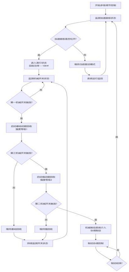
Figure 4 shows a multi-stage adjustment control flowchart based on mechanical switches. This diagram closely integrates software logic with the hardware structure shown in Figure 3, detailing how controller 2 responds to the trigger signals of each mechanical switch. In step S304, when the first mechanical switch 131 is triggered, kinetic energy recovery for the foundation strength is initiated. This first mechanical switch 131 shares with the vehicle's original brake light trigger switch 58, which not only simplifies the structure and reduces costs, but also allows the activation of kinetic energy recovery to synchronize with the brake light on-deceleration warning signal, meeting the driver's psychological expectations. In step S305, when the second mechanical switch 132 is triggered, higher-intensity kinetic energy recovery is initiated, providing the operator with clear, stepwise force feedback. Finally, in step S306, when maximum braking force is required and the brake pedal 14 is pressed deeply to trigger the third mechanical switch 133, the controller (VCU) 2 commands the mechanical braking system 4 to intervene.
Figure 5 illustrates the principle of the brake pedal device based on a mechanical switch, explaining the working mechanism of the mechanical switch structure in Figure 3. This diagram effectively connects the mechanical structure (Figure 3) with the control logic (Figure 4), illustrating how the hardware converts the driver's pedal force into command signals recognizable by the controller (VCU)2. Figure 5 shows how the brake pedal arm contacts the trigger buttons of each mechanical switch in sequence when displacement occurs when the arm is pressed down. This physical contact causes the circuit state of the switch to change (such as switching from open to closed), thereby sending a clear, digital electrical signal to the controller (VCU) 2. In this schematic, the trigger of each switch is directly related to its specific position on the fixed bracket 134, and it is precisely this positional difference that determines its "trigger stroke."
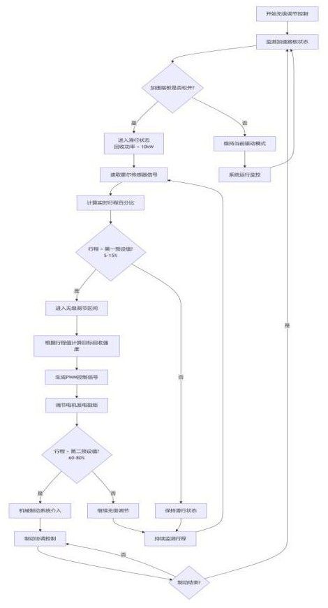
Figure 6 shows the control flowchart of the brake pedal device based on Hall sensors, illustrating the control logic of the stepless adjustment scheme. The main reason lies in step S204: "steplessly adjusting the intensity of kinetic energy recovery based on continuous travel signals." "Stepless adjustment" means the recovery strength can achieve a continuous and smooth proportional change with the brake pedal stroke, which sharply contrasts with the "multi-level" discrete control of the mechanical switch scheme in Figure 4. The adjustment method of controller (VCU) 2 is "to regulate the generation torque of the drive motor by generating PWM (Pulse Width Modulation) signals." This control method delivers the "smoothness of driving and passenger comfort" emphasized in the implementation, eliminating the dragging sensation caused by traditional modes, as it perfectly matches deceleration and pedal travel, resulting in more linear and delicate response.
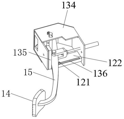
Figure 7 is a schematic diagram of the brake pedal device structure based on Hall sensors. This figure shows the hardware structure implementing the stepless adjustment control scheme in Figure 6. It specifically demonstrates the physical composition of the Hall sensor assembly: Hall element 121 can be slidably installed on the inner wall of the fixed bracket 134 along with the brake pedal 14 (the inner wall of the fixed bracket 134 has a transverse slot 136, which can be slidably located in the transverse slot 136 and is equipped with a reset spring so that when no external force is applied, it returns to its initial position), while the magnet 122 is fixed to the fixed bracket 134, Its magnetic strength shifts from weak to strong at the sliding start to end position along the Hall element 121. When the brake pedal 14 is pressed, the brake pedal arm 15 rotates and pushes the Hall element 121 to slide along the transverse sliding groove 136, changing the relative position and air clearance between the magnet 122 and the Hall element 121, thereby causing the magnetic field strength passing through the Hall element 121 to change continuously and linearly. This structure maps pedal travel, a mechanical force, directly to a continuously changing physical field (magnetic field).
Figure 8 illustrates the principle of the brake pedal device based on Hall sensors. This diagram explains the working mechanism of the structure shown in Figure 7 from the perspective of electromagnetic induction principles. It shows the change in magnetic field distribution generated near Hall element 121 as magnet 122 moves with the brake pedal 14. According to the Hall effect, this changing magnetic field causes Hall element 121 to generate an analog voltage signal proportional to the magnetic field strength, which in turn is proportional to the brake pedal 14 strokes. Figure 8 establishes a key bridge between hardware structure (Figure 7) and control algorithms (Figure 6), mainly illustrating the complete conversion chain from mechanical displacement to continuous electrical signals, and then to stepless control instructions.
Figure 9 shows a multi-stage adjustment control flowchart based on mechanical switches. This diagram is a further refinement or another visual representation of the control flow in Figure 4, once again demonstrating the control logic approach based on the mechanical switch scheme. Specifically, starting from the "coasting state," it progressively improves through "basic recovery strength," "higher recovery strength," and "maximum recovery strength," ultimately reaching a complete control path called "mechanical brake intervention."
Figure 10 shows a stepless regulation control flowchart based on Hall sensors. Similarly, this diagram supplements and emphasizes the stepless regulation process in Figure 6. It highlights the continuous control feature of transitioning directly from "gliding state" to "stepless adjustment of recovery intensity." This demonstrates the flexibility of this utility model in achieving precise recovery control.
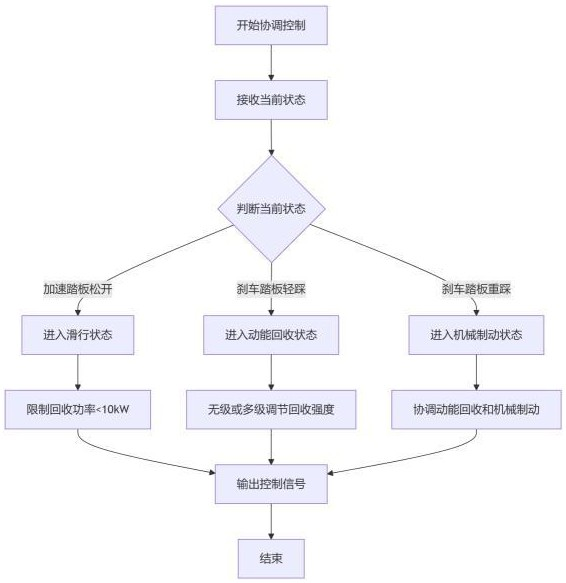
Figure 11 is a system coordination control flowchart. This diagram focuses on a higher-level and crucial technical issue: the coordination between the automotive energy recovery system 3 and the mechanical braking system 4. When the brake pedal 14 is deeply pressed to the second preset stroke, "the controller (VCU) 2 will control the mechanical braking system 4 to intervene, providing braking force together or independently with the vehicle's kinetic energy recovery system 3." The process in Figure 11 precisely describes how the Controller (VCU)2 intelligently allocates and coordinates the braking force output of both systems based on the brake pedal travel14 and vehicle status, ensuring smooth, stable, and efficient braking. It addresses key issues common in hybrid braking systems, such as sudden changes in braking force and abnormal pedal feel, and is the core link in achieving the two beneficial effects of "ensuring braking safety" and "improving driving comfort."
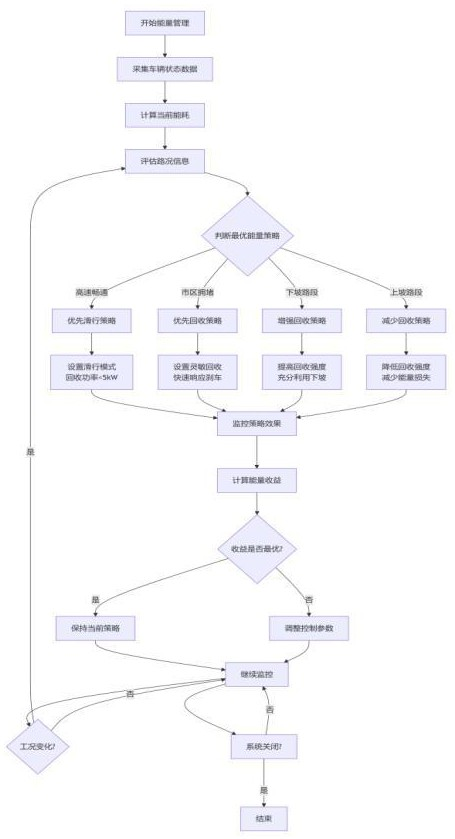
Figure 12 Energy Management Optimization Flowchart, from a strategic perspective on vehicle energy management, summarizes the overall optimization approach of this utility model. It places the main control process in Figure 2 under a more macro "energy optimal" decision-making framework. The process begins with assessing driving conditions: when deceleration is needed, should kinetic energy recovery be prioritized or priority is maintained by maintaining inertia; Under coasting conditions (accelerator pedal released), inertia is maximized, and only when there is a clear intention to decelerate (brake pedal 14) does it "on-demand" start and optimize kinetic energy recovery.
Specifically, Figure 12 shows the complete decision-making and execution loop of the energy management optimization strategy of this utility model. The process starts with "starting energy management," where the system first continuously "collects vehicle status data," and based on this, "calculates current losses" and "evaluates energy information." After integrating this information, the system enters the "Optimal Energy Strategy Judgment" stage, during which the system calls a preset "measurement model" and references real-time road information such as "urban measurements," "downhill sections," and "uphill sections," combined with "priority path prediction" to make decisions.
Based on the outcome of the strategy, the system will activate the corresponding recycling mode: for example, selecting "Priority Gliding Strategy" (highway traffic clearance), "Priority Recycling Strategy" (urban congestion), "Enhanced Recycling Strategy" (downhill sections), or "Reduced Recycling Strategy" (uphill sections). These strategies are implemented through specific execution instructions, including "setting path mode," "setting sensitive recycling," "increasing recycling speed," or "reducing recycling intensity." The execution goals are clear, such as ensuring "5kW power recovery < 5kW" during taxiing to achieve "rapid response efficiency," fully utilizing downhill potential and "reducing energy loss" during downhill driving.
After the strategy is executed, the system enters the "Monitoring Strategy Effectiveness" stage, quantifying results by "calculating energy returns" and continuously asking itself, "Is the benefit optimal?" ”。 If the optimal method is not achieved, "adjust control parameters" and "continue monitoring" to form an iterative optimization loop; If optimal, "maintain the current strategy." The system continuously monitors "Changes in operating conditions?" throughout the entire process. Until it receives the message "System shutdown?" "Directive, ultimately 'end' the entire energy management process." This flowchart clearly reveals how the system dynamically senses, makes intelligent decisions, executes precisely, and continuously optimizes to maximize energy recovery efficiency across all scenarios.
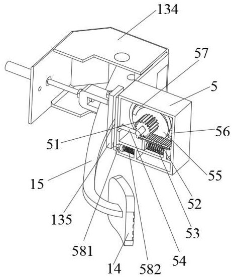
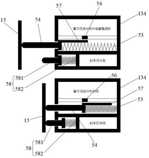
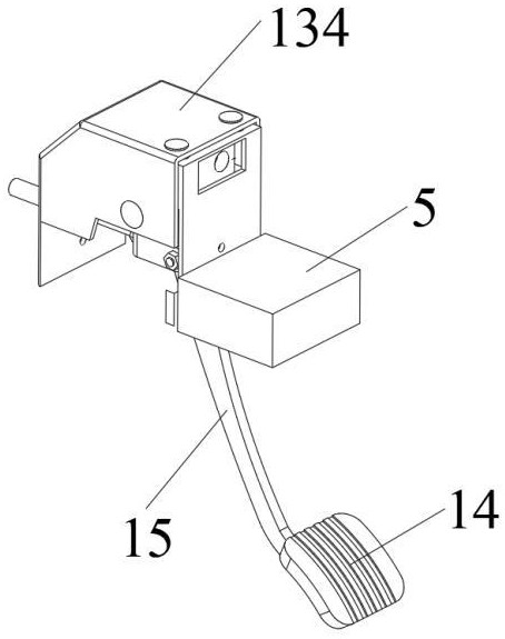
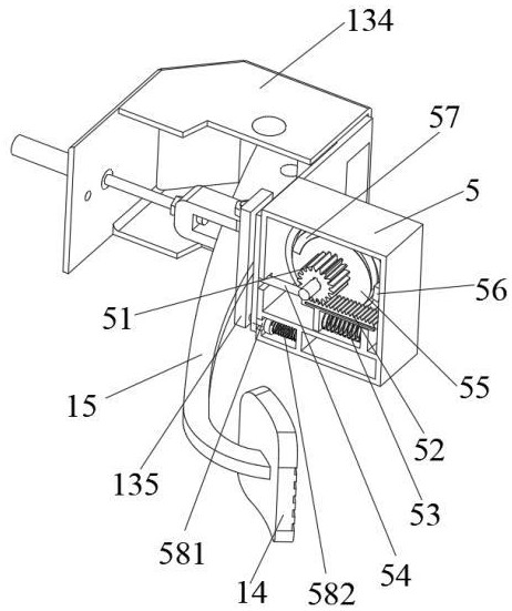
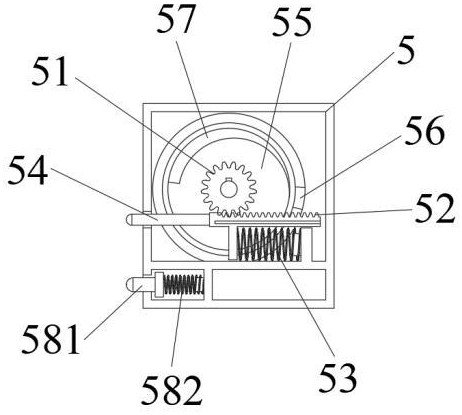
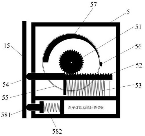
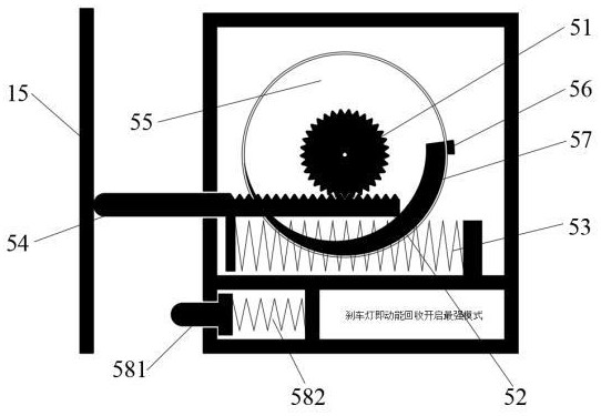
Figures 13-15 show the second brake pedal structure based on Hall sensors, which includes a housing 5, gears 51 installed in housing 5, rack 52, first spring 53, trigger lever 54, turntable 55, Hall sensor 56, magnetic strip 57, and brake light trigger switch 58; The gear 51 is fixedly connected to the turntable 55, and the Hall sensor 56 is installed in the housing 5 and is close to the edge of the turntable 55; The magnetic strips 57 are distributed along the edges of the turntable 55, and their magnetic strength transitions from weak to strong along the edges. The outer surface of the magnetic strips 57 is opposed to the Hall sensor 56 as the turntable 55 rotates. The first spring 53 is arranged laterally in the housing 5, and the trigger rod 54 abuts the end of the first spring 53, with its front end extending outside the housing 5 and separating to the brake pedal arm 15; The rack 52 is connected to the rear end of the trigger rod 54. The brake light trigger switch 58 includes a trigger button 581 and a second spring 582. The second spring 582 is installed on the lower inner side of housing 5. The rear end of trigger button 581 abuts against the second spring 582, and the front end of trigger button 581 extends outside the housing 5. When the brake is not pressed, the trigger button 581 elastically abuts against the brake pedal arm 15. The length of the trigger button 581 extending out from the housing 5 is shorter than the length of the trigger lever 54 extending out from the housing 5.
Figure 16 shows that when the brake is not pressed, the brake pedal arm 15, driven by the reset spring (the automotive brake mechanism itself has a reset spring), presses against the trigger rod 54 and trigger button 581, overcoming the elastic force of the first spring 53 and second spring 582, causing both the trigger rod 54 and trigger button 581 to extend a short distance outside the housing 5. At this time, the Hall sensor 56 and magnetic stripe 57 do not generate an induced magnetic field, nor does kinetic energy recovery trigger; The brake light trigger switch 58 was also not triggered to light up.
Figure 17 shows that when the brake is pressed, the brake pedal arm 15 moves away from the trigger arm 54 and the trigger button 581. The trigger button 581 immediately extends forward from the housing 5 under the drive of the second spring 582, and the brake light turns on; At the same time, the trigger rod 54 extends forward under the first spring 53 drive, driving the rack 52 to rotate, which in turn drives the gear 51 and turntable 55 to rotate. The Hall sensor 53 and magnetic strip 57 generate magnetic induction signals. As the amplitude of the brake pedal 14 increases, the distance from the housing 54 of the trigger rod 54 increases. The magnetic induction signal generated by the Hall sensor 53 and the magnetic strip 57 gradually strengthens as the magnetic field strength increases and is sent to the vehicle's control unit (VCU). Triggers greater kinetic recovery intensity.
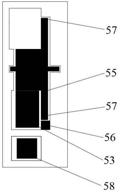
Figure 18 shows a cross-sectional view of the Hall sensor 53 and magnetic strip 57 in operation, further clearly illustrating the principle behind magnetic induction changes caused by the relative position and rotational tendency of the Hall sensor 53 and magnetic strip 57.
It should be noted that in the above embodiments, a trigger plate 135 is provided near the brake pedal arm 15 near the brake light trigger switch 58 and the mechanical switch 13/trigger rod. The trigger plate 135 allows the brake pedal 14 to remain more securely in an untriggered state when not pressed, and when the brake pedal 14 is pressed, the contact surface of the trigger plate 135 makes the triggering smoother and more orderly.
Additionally, it should be noted that this utility model has discovered and verified an important safety advantage in actual testing, especially under conditions of low adhesion coefficient road surfaces (such as rainy days or icy or snowy roads). When a vehicle needs emergency braking on slippery roads, traditional mechanical braking systems that apply large braking force directly can cause wheel lock-up, slip, or even instability due to sudden saturation of the tire-ground grip. This not only extends braking distance but also seriously threatens the vehicle's handling stability. The control strategy proposed by this utility model, namely "first initiating strong kinetic energy recovery, then coordinating or continuing mechanical braking," provides an innovative solution to this problem.
The technical principle lies in the fundamental difference in mechanical properties between kinetic energy recovery systems (i.e., motor braking) and traditional friction braking. The motor braking torque is precisely and rapidly generated and regulated by the motor controller through power electronic devices, with a response delay far shorter than the time it takes for the hydraulic braking system to establish pressure. When the driver urgently presses the brake pedal on a slippery road, the system prioritizes applying strong electric braking force generated by the drive motor based on travel information (whether triggered steplessly via Hall sensors or multi-stage triggered by mechanical switches). This electric braking force has two key characteristics: first, it responds extremely quickly and controllably, providing almost instantaneous smooth and linear deceleration, avoiding shocks caused by the hydraulic system building up too quickly; Second, motor braking force naturally makes it easier to coordinate with the vehicle's stability control systems (such as ESC/ESP). By independently or differentially adjusting the torque of the left and right drive wheels (which is especially effective on vehicles with dual motors), it can actively suppress potential wheel slip at the initial deceleration stage, creating a more stable initial deceleration posture for the vehicle.
Then, when the brake pedal travel deepens further, the mechanical braking system engages. At this point, the vehicle's speed has been reduced due to the electric brakes, and the body dynamics are more stable. The mechanical braking system adds braking force on top of this stability, making the deceleration curve smoother throughout the braking process and greatly increasing the likelihood of tire slip rate being controlled within the optimal range. This effectively avoids the risk of loss of control caused by the traditional method, where hydraulic braking forces are suddenly applied and tire friction limits are easily exceeded on low-adhesion roads. In short, this utility model combines the advantages of fast and easy-to-control electric braking with emergency braking scenarios, setting a controllable "forward buffer phase" dominated by electric braking in the braking sequence, thereby significantly enhancing the safety and controllability of emergency braking on slippery roads. This effect is not subjective speculation but objectively verified in actual road slippery condition tests by comparing vehicle wheel speed signals, yaw angular speed, and body trajectory under traditional and current braking modes, manifesting as significant improvements in braking distance stability and directional controllability. This further reflects the core concept of "on-demand recycling and pedal coordination" of this utility model, which not only effectively improves range but also expands its technical value in active safety.
The design focus of this utility model is, first, by eliminating strong kinetic energy recovery during coasting, effectively avoiding inertial coasting interruptions caused by recovered braking force. Actual road tests have verified that this change can directly increase driving range by 4% to 7% under high-speed conditions. Second, by precisely controlling recovery intensity steplessly or in multiple stages of the brake pedal travel, it achieves precise matching between energy recovery and deceleration needs. This not only optimizes energy recovery efficiency (expected to recover 5% to 10% more electricity) but also greatly improves driving smoothness and passenger comfort, eliminating the dragging sensation caused by traditional modes. Finally, this method unifies deceleration intention with execution actions on the brake pedal, aligning with the driver's natural instincts, making operation intuitive and helping to enhance driving safety.
The above descriptions are merely preferred embodiments of this utility model and do not limit the technical scope of this utility model. Therefore, any minor modifications, equivalent changes, or modifications made to the above embodiments based on the technical essence of this utility model still fall within the scope of the technical solutions of this utility model.










 400-4929-0909
 contact@catarc.com.cn