Invention content
The present invention is intended to at least solve a technical problem existing in the prior art, for this purpose, the first aspect of the present invention proposes a method for extracting a lane reference line, the method comprising:
Obtain pavement point cloud data, the pavement point cloud data is the point cloud data on the road surface collected by the collection vehicle during driving, and the pavement includes a plurality of lane lines;
obtain the starting point and root node from the pavement point cloud data, and the starting point and the root node are two points on the manually preconfirmed lane line; The direction from the starting point to the root node is consistent with the direction of travel of the collection vehicle; the manually preconfirmed lane line is one of the multiple lane lines;
Obtain the first trajectory data composed of the driving trajectory point of the acquisition vehicle, and determine the first trajectory point closest to the root node from the first trajectory data;
Taking the first trajectory point as the center point, the pavement point cloud data within the preset radius of the center point is preloaded, and the pre-loaded pavement point cloud data is denoising to obtain the first point cloud data;
Obtain the acquisition timestamp of the root node, and in the case of the corresponding first trajectory data within the preset time range of the acquisition timestamp, the search direction of the new node is determined based on the forward direction of the first trajectory point;
Starting from the root node, the new node is searched from the first point cloud data according to the search direction and the preset search step;
update the first trajectory point to the new node, starting with the new node, continue to perform the denoising processing and search for the next new node;
Route reference lines are generated based on the origin point, the root node and a plurality of new nodes obtained by searching.
Optionally, the search direction of the new node is determined based on the forward direction of the first trajectory point, comprising:
Obtain two points adjacent to the first trajectory point from the first trajectory data to obtain the first pre-point and the first posterior point, the first pre-point is the trajectory point of the previous moment corresponding to the first trajectory point, and the first post-point is the trajectory point of the next moment corresponding to the first trajectory point;
obtain the angle between the first direction determined by the starting point and the root node, and the second direction determined by the first pre-point and the first post-point;
determine the first distance between the first trajectory point and the root node;
Based on the first distance, the angle determines the search direction of the new node.
optionally, the search direction of the new node is determined based on the first distance, the angle between the angle, comprising:
If the first distance is greater than or equal to the preset first distance threshold, or the angle is greater than or equal to the preset angle threshold, the direction determined by the starting point and the root node is determined as the search direction of the new node; The first distance threshold is the distance traveled by the acquisition vehicle in P trajectory data acquisition cycles;
If the first distance is less than the preset first distance threshold, and the angle is less than the preset angle threshold, the search direction of the new node is determined based on the first trajectory point, the first front point, and the first back point.
optionally, the search direction of the new node is determined based on the first trajectory point, the first pre-point, and the first post-point, comprising:
determine the second distance between the first posterior point and the first trajectory point;
If the second distance is greater than or equal to the preset second distance threshold, the direction determined by the first pre-point and the first post-point is used as the search direction of the new node; The second distance threshold is the distance traveled by the acquisition vehicle in Q trajectory data acquisition cycles, Q>P;
If the second distance is less than the second distance threshold, the first trajectory point is updated to the first postpoint, and the direction determined by the pre and posterior points of the first postpoint is taken as the search direction of the new node.
Optionally, after obtaining the acquisition timestamp of the root node, it also includes:
In the case of no corresponding first trajectory data within the preset time range of the acquisition timestamp, the direction determined by the starting point and the root node will be used as the search direction of the new node.
Optionally, the preloaded pavement point cloud data is denoising processing, comprising:
The preloaded pavement point cloud data is sorted by the point cloud reflection intensity;
The point cloud data sorted in the top N% and the point cloud data sorted in the last M% are filtered from the pavement point cloud data to obtain the primary processing point cloud data; The point cloud data sorted in the first N% is the point cloud data corresponding to the foreign object on the road surface, the point cloud data sorted in the last M% is the point cloud data corresponding to the ordinary road surface, and the initial processing point cloud data is the point cloud data corresponding to the lane line;
The spatial area corresponding to the initial processing point cloud data is divided according to the preset grid size to obtain a plurality of point cloud meshes;
According to the size relationship between the number of point clouds included in the point cloud grid and the preset first quantity threshold, each point cloud grid is initially binarized marked, and the plurality of point cloud grids are corroded and expanded according to the initial binarization marking results, and a plurality of point cloud meshes including target binarization marking results are obtained;
According to the target binarization labeling results, the target point cloud grid greater than or equal to the first quantity threshold is obtained, and the point cloud data in the target point cloud grid is determined to be the first point cloud data.
optionally, according to the size relationship between the number of point clouds included in the point cloud grid and the preset first quantity threshold, the initial binarization mark of each point cloud grid, and the plurality of point cloud grids are corroded and expanded according to the initial binarization marking results, comprising:
The point cloud grid included in the point cloud grid where the number of point clouds is less than the first quantity threshold is marked as P, and the point cloud grid with the number of point clouds greater than or equal to the first quantity threshold is marked as Q to obtain the initial binary labeling result;
According to the initial binarization labeling results, the plurality of point cloud grids are subjected to multiple corrosion treatment and multiple expansion treatments, respectively, and a plurality of point cloud grids including the target binarization marking results are obtained;
The point cloud data in the point cloud grid with the target binarization mark result of Q is determined to be the first point cloud data.
Optionally, the new node is searched from the first point cloud data starting from the root node, according to the search direction and the preset search step, comprising:
Starting from the root node, the next node is determined from the first point cloud data according to the search direction and the preset search step;
determine whether the next node satisfies the target condition, the target condition is: the number of point clouds in the point cloud grid to which the node belongs is greater than or equal to the preset second quantity threshold; the second quantity threshold is greater than the first quantity threshold;
If the next node satisfies the target condition, the average of the coordinate values of each point cloud in the point cloud grid is determined, and the average value is used as the coordinate value of the new node.
Optionally, after determining whether the next node meets the target condition, also includes:
If the next node does not meet the target conditions, the search step is increased to continue to determine the new next node from the first point cloud data;
determine whether the new next node satisfies the target condition;
If the target condition is not met, the search step is continued to increase, and the new next node is determined from the first point cloud data until the new next node meets the target condition, or the search reaches the preset stopping condition.
Optional, the preset stop conditions include:
The new node has reached the intersection;
The search direction of the new node is opposite to the direction of travel of the collection vehicle;
The third distance between the new node and the nearest existing reference line start node is less than the third distance threshold; The existing reference line is the reference line of the same direction lane;
The search step of the new node exceeds the preset step threshold.
Optionally, after extracting and generating lane reference lines based on the start point, the root node, and a plurality of searched new nodes, it also includes:
Based on the position relationship between the reference line and each lane line, the preset lane width generates a plurality of lane lines of the road surface.
The second aspect of the present invention proposes a lane reference line extraction device, comprising:
Pavement point cloud data acquisition module for obtaining pavement point cloud data, the pavement point cloud data is the point cloud data on the road surface collected by the collecting vehicle during driving, and the pavement includes a plurality of lane lines;
The starting point root node acquisition module is used to obtain the starting point and the root node from the pavement point cloud data, and the starting point and the root node are two points on the manually preconfirmed lane line; The direction from the starting point to the root node is consistent with the direction of travel of the collection vehicle; the manually preconfirmed lane line is one of the multiple lane lines;
the first trajectory point determination module for obtaining the first trajectory data composed of the driving trajectory point of the acquisition vehicle, and determining the first trajectory point closest to the root node from the first trajectory data;
The denoising processing module is configured to take the first trajectory point point as the center point, preload the pavement point cloud data within the preset radius of the center point, and denoise the preloaded pavement point cloud data to obtain the first point cloud data;
The first search direction determination module is used to obtain the acquisition timestamp of the root node, and in the case of the corresponding first trajectory data within the preset time range of the acquisition timestamp, the search direction of the new node is determined based on the forward direction of the first trajectory point;
a new node search module for searching for the new node from the first point cloud data starting from the root node, according to the search direction and the preset search step;
an update module for updating the first trajectory point to the new node, starting with the new node, continuing to perform the denoising processing and search for the next new node;
The lane guide generation module is used to extract and generate a lane guide based on the start point, the root node and a plurality of new nodes obtained by searching.
Optionally, the first search direction determines the module specifically used for:
Obtain two points adjacent to the first trajectory point from the first trajectory data to obtain the first pre-point and the first posterior point, the first pre-point is the trajectory point of the previous moment corresponding to the first trajectory point, and the first post-point is the trajectory point of the next moment corresponding to the first trajectory point;
obtain the angle between the first direction determined by the starting point and the root node, and the second direction determined by the first pre-point and the first post-point;
determine the first distance between the first trajectory point and the root node;
Based on the first distance, the angle determines the search direction of the new node.
Optionally, the first search direction determination module is further used for:
If the first distance is greater than or equal to the preset first distance threshold, or the angle is greater than or equal to the preset angle threshold, the direction determined by the starting point and the root node is determined as the search direction of the new node; The first distance threshold is the distance traveled by the acquisition vehicle in P trajectory data acquisition cycles;
If the first distance is less than the preset first distance threshold, and the angle is less than the preset angle threshold, the search direction of the new node is determined based on the first trajectory point, the first front point, and the first back point.
Optionally, the search direction determination module is further used for:
determine the second distance between the first posterior point and the first trajectory point;
If the second distance is greater than or equal to the preset second distance threshold, the direction determined by the first pre-point and the first post-point is used as the search direction of the new node; The second distance threshold is the distance traveled by the acquisition vehicle in Q trajectory data acquisition cycles, Q>P;
If the second distance is less than the second distance threshold, the first trajectory point is updated to the first postpoint, and the direction determined by the pre and posterior points of the first postpoint is taken as the search direction of the new node.
Optionally, the device further comprises:
The second search direction determination module is configured to use the direction determined by the starting point and the root node as the search direction of the new node in the absence of corresponding first trajectory data within the preset time range of the acquisition timestamp.
Optionally, the denoising processing module is specifically used for:
The preloaded pavement point cloud data is sorted by the point cloud reflection intensity;
The point cloud data sorted in the top N% and the point cloud data sorted in the last M% are filtered from the pavement point cloud data to obtain the primary processing point cloud data; The point cloud data sorted in the first N% is the point cloud data corresponding to the foreign object on the road surface, the point cloud data sorted in the last M% is the point cloud data corresponding to the ordinary road surface, and the initial processing point cloud data is the point cloud data corresponding to the lane line;
The spatial area corresponding to the initial processing point cloud data is divided according to the preset grid size to obtain a plurality of point cloud meshes;
According to the size relationship between the number of point clouds included in the point cloud grid and the preset first quantity threshold, each point cloud grid is initially binarized marked, and the plurality of point cloud grids are corroded and expanded according to the initial binarization marking results, and a plurality of point cloud meshes including target binarization marking results are obtained;
According to the target binarization labeling results, the target point cloud grid greater than or equal to the first quantity threshold is obtained, and the point cloud data in the target point cloud grid is determined to be the first point cloud data.
Optionally, the denoising processing module is further configured for:
The point cloud grid included in the point cloud grid where the number of point clouds is less than the first quantity threshold is marked as P, and the point cloud grid with the number of point clouds greater than or equal to the first quantity threshold is marked as Q to obtain the initial binary labeling result;
According to the initial binarization labeling results, the plurality of point cloud grids are subjected to multiple corrosion treatment and multiple expansion treatments, respectively, and a plurality of point cloud grids including the target binarization marking results are obtained;
The point cloud data in the point cloud grid with the target binarization mark result of Q is determined to be the first point cloud data.
Optionally, the new node search module is specifically used to:
Starting from the root node, the next node is determined from the first point cloud data according to the search direction and the preset search step;
determine whether the next node satisfies the target condition, the target condition is: the number of point clouds in the point cloud grid to which the node belongs is greater than or equal to the preset second quantity threshold; the second quantity threshold is greater than the first quantity threshold;
If the next node satisfies the target condition, the average of the coordinate values of each point cloud in the point cloud grid is determined, and the average value is used as the coordinate value of the new node.
Optionally, the new node search module is specifically used to:
If the next node does not meet the target conditions, the search step is increased to continue to determine the new next node from the first point cloud data;
determine whether the new next node satisfies the target condition;
If the target condition is not met, the search step is continued to increase, and the new next node is determined from the first point cloud data until the new next node meets the target condition, or the search reaches the preset stopping condition.
Optionally, the device further comprises:
Lane line generation module for generating multiple lane lines of the road surface based on the position relationship between the reference line and each lane line, preset lane width.
A third aspect of the present invention proposes an electronic device, the electronic device comprising a processor and memory, the memory stored at least one instruction or at least one program, at least one instruction or at least one program loaded by the processor and executed to achieve the lane guide as in the first aspect of the extraction method.
A fourth aspect of the present invention proposes a computer-readable storage medium in which at least one instruction or at least one segment of programs is stored therein, and at least one instruction or at least one segment of programs is loaded and executed by the processor to achieve the extraction method of the lane reference line as described in the first aspect.
Embodiments of the present invention have the following beneficial effects:
In an embodiment of the present invention, the pavement point cloud data is obtained, the pavement point cloud data is the point cloud data on the road surface collected by the collecting vehicle during driving, and the road surface includes a plurality of lane lines; Obtain the starting point and root node from the pavement point cloud data; Obtain the first trajectory data composed of the driving trajectory point of the acquisition vehicle, and determine the first trajectory point closest to the root node from the first trajectory data; Taking the first trajectory point as the center point, the pavement point cloud data within the preset radius of the center point is preloaded, and the pre-loaded pavement point cloud data is denoising to obtain the first point cloud data; Obtain the acquisition timestamp of the root node, and in the case of the corresponding first trajectory data within the preset time range of the acquisition timestamp, the search direction of the new node is determined based on the forward direction of the first trajectory point; Starting from the root node, the new node is searched from the first point cloud data according to the search direction and the preset search step; update the first trajectory point to the new node, starting with the new node, continue to perform the denoising processing and search for the next new node; Route reference lines are generated based on the origin point, the root node and a plurality of new nodes obtained by searching. The above method uses computer algorithm to search for new nodes, which improves the generation efficiency of reference lines. The starting point and root node of the reference line are selected from the point cloud data corresponding to the preconfirmed lane line, and the selection accuracy of the starting point and root node is improved based on the manual technical reserve. Moreover, based on the forward direction of the first trajectory data, the search direction of the new node of the reference line is determined, so that the search direction of the reference line is consistent with the driving direction of the collection vehicle, which ensures the accuracy of the search direction and the accuracy of the reference line.
Specific embodiment
The following will be combined with the accompanying drawings in the embodiments of the present invention, the technical solution in the embodiments of the present invention is clearly and completely described, obviously, the described embodiments are only a part of the embodiments of the present invention, not all embodiments. Based on embodiments in the present invention, all other embodiments obtained by those of ordinary skill in the art without making creative labor, fall within the scope of protection of the present invention.
Hereinafter, the terms "first" and "second" are for descriptive purposes only and cannot be understood as indicating or implying relative importance or implicitly indicating the number of technical features indicated. Thus, the features limited to "first" and "second" may explicitly or implicitly include one or more of the features. In the description of the present public embodiment, unless otherwise stated, "plurality" means two or more. Further, the use of "based on" or "based on" means open and inclusive, because processes, steps, calculations or other actions "based on" or "according to" one or more of the said conditions or values may, in practice, be based on additional conditions or exceed the stated values.
FIG 1 is one of the flowcharts of a lane reference line extraction method provided by an embodiment of the present invention, the method may comprise the following steps:
Step 101, obtain the pavement point cloud data, the pavement point cloud data is the point cloud data on the road surface collected by the collecting vehicle during driving, the pavement includes a plurality of lane lines.
The high-precision map collection vehicle collects the point cloud data of the entire road surface during the driving process on the road surface to obtain the road surface point cloud data. The pavement point cloud data includes the point cloud information of all objects on the pavement, such as the pavement, lane lines on the pavement, foreign objects on the pavement, and so on.
Each point in the pavement point cloud data includes information such as three-dimensional coordinates, acquisition timestamps, color information (RGB values), and reflection intensity information (IQteQsity).
Step 102, obtain the starting point and the root node from the pavement point cloud data, the starting point and the root node are two points on the manually preconfirmed lane line; The direction from the starting point to the root node is consistent with the direction of travel of the collection vehicle; The manually preconfirmed lane line is one of the plurality of lane lines.
The start point and root node are used as the first two points to generate a lane reference line, hereinafter referred to as a guide. The start point and root nodes here are extracted from the manually preconfirmed lane lines, so the reference line that this scenario ultimately generates is one of the lane lines.
The guides in this scenario are reference identifiers that generate other lane lines on the pavement and are used as direction and length references for generating other lane lines. After obtaining the reference lines, other lane lines on the road surface can be obtained by copying the panning method.
In related technology, a lane line is obtained by all manual clicks, and the lane line is used as a reference line to generate other lane lines, but there are two main problems in this method. First, manual selection is less efficient and time-consuming; Second, the reference line needs to be in the very center of the lane line, but the reference line generated by manual clicking has a certain width, and it is impossible to be accurately in the center of the lane line, so it will cause errors.
In this scheme, after obtaining the road point cloud data, the point cloud data belonging to the lane line is identified by the human eye, that is, the preconfirmed lane line is obtained through the human eye, and then two points are randomly selected from the preconfirmed lane line as the starting point and root node. Subsequently, the root node is used as the search basis for the next node, and other nodes on the search reference line are tracked by computer algorithms.
Selecting the entire lane line from the road point cloud data will cause errors, but it is easy and accurate to select two points from the lane line, compared with computer selection, this method uses human technical reserve point selection, improves the efficiency and accuracy of point selection, and provides an accurate starting point for subsequent tracking search.
It is understood that a computer can also be used to obtain preconfirmed lane lines, or a computer can be used to select the starting point and root node from the preconfirmed lane lines, and this scheme does not specifically limit this.
Specifically, assuming that the starting point is P1 and the root node is P2, the direction of the vector must be consistent with the driving direction of the acquisition vehicle, so that the direction![]() of the reference line obtained by subsequent tracking can be consistent with the driving direction.
of the reference line obtained by subsequent tracking can be consistent with the driving direction.
FIG 2 is a schematic view of a lane line provided by an embodiment of the present invention.
As shown in Figure 2, the road point cloud data includes three lane lines, and the rightmost lane line is selected as the preconfirmed lane line, which will be used as the reference line to be extracted. Pick two points from the preconfirmed lane line to serve as the start point and root node.
Step 103, obtain the first trajectory data composed of the driving trajectory point of the acquisition vehicle, and determine the first trajectory point closest to the root node from the first trajectory data.
In the process of tracking the next node of the search reference line, the direction and location of the next node is not clear, it is possible that the road has turned, but the pavement point cloud data is still extended.
During the process of the collection vehicle driving on the road, a series of GPS trajectory points will be formed. The trajectory of the collection vehicle is consistent with the direction of the road, and the driving trajectory of the collection vehicle can provide guidance for the search for the next node. Therefore, the driving track can be used as an important reference for searching for the next node to improve the search efficiency and prevent the search direction from deviating.
In an embodiment of the present invention, the GPS trajectory point coordinates of the acquisition vehicle can be obtained every certain period (such as 0.1 seconds) to obtain the first trajectory data. The first trajectory data specifically includes the coordinates of each trajectory point and the corresponding acquisition timestamp.
The pavement point cloud data specifically includes the three-dimensional coordinates and acquisition timestamps of each object on the pavement, so the two-dimensional coordinates corresponding to the root node in the pavement dimension can be determined. The two-dimensional coordinates of the root node and the coordinates of each trajectory point are used to determine the Euclidean distance between each trajectory point and the root node, and the trajectory point with the smallest Euclidean distance is selected as the first trajectory point.
For example, suppose that the starting point and root node are selected P1 and P2, respectively, determine the Euclidean distance between each trajectory point and P2 point, and select the trajectory point G1, which has the smallest Euclidean distance from P2 point, as the first trajectory point.
Step 104, taking the first trajectory point as the center point, preload the pavement point cloud data within the preset radius of the center point, and denoise the preloaded pavement point cloud data to obtain the first point cloud data.
Take the first trajectory point as the center point of the preloaded point cloud, set the radius R1 of the loaded point cloud, and read the pavement point cloud data within this radius.
Since the pavement point cloud data may include noise such as standing water and falling leaves, it is necessary to filter out the noise of the read pavement point cloud data to obtain the first point cloud data.
Step 105, obtain the acquisition timestamp of the root node, and in the case of the corresponding first trajectory data within the preset time range of the acquisition timestamp, based on the forward direction of the first trajectory point, determine the search direction of the new node.
The driving trajectory of the collection vehicle is consistent with the forward direction of the road, so the driving trajectory of the collection vehicle at a certain time is consistent with the forward direction of the lane line at that moment, and the driving trajectory of the collection vehicle can provide guidance for the next node of the search reference line.
Firstly, the acquisition timestamp is obtained from the point cloud information of the root node to confirm whether the first trajectory data exists within the preset time range of the acquisition timestamp. The preset time range can be taken from a smaller time range such as 0.1 seconds and 0.05 seconds.
If the first trajectory data exists within the preset time range, the forward direction of the first trajectory data can be used as the reference basis for determining the search direction.
Step 106, starting from the root node, according to the search direction and the preset search step, search for the new node from the first point cloud data.
After confirming the direction of the search, you need to set the search step size. The search step size can be set to a fixed value or to a value that changes depending on the search situation. In addition, the search direction can also be set to change with the search situation.
Starting from the root node, search for new nodes from the first point cloud data based on search direction and search step.
Step 107, the first trajectory point is updated to the new node, starting with the new node, continue to perform the denoising processing and search for the next new node operation.
After the new node is found, denoising and searching for the next new node are performed with the new node as the central point.
Specifically, with the new node as the central point, the pavement point cloud data within the preset radius of the new node is preloaded, and the preloaded pavement point cloud data is denoising to obtain the second point cloud data. Obtain the acquisition timestamp of the new node, and determine the search direction of the next new node based on the forward direction of the first trajectory point when the corresponding first trajectory data is available within the preset time range of the acquisition timestamp.
Starting from the new node, search for the next new node from the second first point cloud data according to the search direction of the next new node and the preset search step.
Repeat the preceding steps until the stop condition is triggered, and then stop the search. During multiple searches, multiple new nodes are obtained that extend sequentially in the direction of the lane line.
Step 108, based on the starting point, the root node and a plurality of search new nodes extracted to generate a lane reference line.
The start point, root node and each new node obtained by the search are extracted from the road point cloud data, and the nodes are connected to obtain the lane guide line.
In summary, in an embodiment of the present invention, the pavement point cloud data is obtained, the pavement point cloud data is the point cloud data on the road surface collected by the collecting vehicle during driving, and the pavement comprises a plurality of lane lines; Obtain the starting point and root node from the pavement point cloud data; Obtain the first trajectory data composed of the driving trajectory point of the acquisition vehicle, and determine the first trajectory point closest to the root node from the first trajectory data; Taking the first trajectory point as the center point, the pavement point cloud data within the preset radius of the center point is preloaded, and the pre-loaded pavement point cloud data is denoising to obtain the first point cloud data; Obtain the acquisition timestamp of the root node, and in the case of the corresponding first trajectory data within the preset time range of the acquisition timestamp, the search direction of the new node is determined based on the forward direction of the first trajectory point; Starting from the root node, the new node is searched from the first point cloud data according to the search direction and the preset search step; update the first trajectory point to the new node, starting with the new node, continue to perform the denoising processing and search for the next new node; Route reference lines are generated based on the origin point, the root node and a plurality of new nodes obtained by searching. The above method uses computer algorithm to search for new nodes, which improves the generation efficiency of reference lines, selects the starting point and root node of the reference line from the point cloud data corresponding to the preconfirmed lane line, and improves the selection accuracy of the starting point and root node. Moreover, based on the forward direction of the first trajectory data, the search direction of the new node of the reference line is determined, so that the search direction of the reference line is consistent with the driving direction of the collection vehicle, which ensures the accuracy of the search direction.
In one possible embodiment, as shown in FIG. 3, in step 105, based on the forward direction of the first trajectory point, the search direction of the new node is determined, comprising:
Step 1051, from the first trajectory data to obtain two points adjacent to the first trajectory point before and after, obtain the first front point and the first back point, the first front point is the trajectory point of the previous moment corresponding to the first trajectory point, the first rear point is the trajectory point of the next moment corresponding to the first trajectory point.
The first trajectory data includes the coordinates of each trajectory point and the acquisition timestamp, according to the acquisition timestamp, the locus point coordinates of the previous moment of the first trajectory point and the coordinates of the trajectory point of the next moment can be obtained, that is, the coordinates of the first front point and the coordinates of the first back point.
Step 1052, obtaining the angle between the first direction determined by the starting point and the root node, and the second direction determined by the first pre-point and the first post-point.
Specifically, the first direction determined by the start point P1 and the root node P2 is![]() .
.
Let the first anterior point of the first trajectory point G1 be G0 and the first posterior point be G2, then the second direction determined by the first precedent and first posterior points is![]() .
.
![]() The angle between and
The angle between and![]() is the angle between the first and second directions.
is the angle between the first and second directions.
Step 1053, determine the first distance between the first trajectory point and the root node.
The first distance between the first trajectory point G1 and the root node P2 can be calculated using the Euclidean distance.
Step 1054, based on the first distance, the angle determines the search direction of the new node.
The first distance indicates the distance between the first trajectory point and the root node, and the angle indicates the direction deviation between the forward direction of the first trajectory point and the direction determined by the starting point and the root node, and the possibility that the first trajectory point belongs to the lane line can be determined by the distance and angle. If the first track point is less likely to belong to the lane line, abandon using the first track point to determine the search direction of the new node, and if the first track point is more likely to belong to the lane line, the first track point can be used to determine the search direction of the new node.
In steps 1051-step 1054, the search direction of the new node is determined based on the first distance and the angle, so that the search direction of the new node can be determined according to the distance between the first trajectory point and the root node, and at the same time according to the angle between the first direction and the second direction, so that the decision of the search direction is more scientific and reasonable, and the accuracy of the search direction determination is guaranteed.
In one possible embodiment, step 1054 comprises:
Step 10541, if the first distance is greater than or equal to the preset first distance threshold, or the angle is greater than or equal to the preset angle threshold, the starting point and the direction determined by the root node are determined as the search direction of the new node; The first distance threshold is the distance traveled by the acquisition vehicle in P trajectory data acquisition cycles.
During the driving process of the acquisition vehicle, the GPS trajectory point coordinates of the acquisition vehicle are obtained every certain cycle (such as 0.1 seconds) to obtain the first trajectory data. The first distance threshold is the distance traveled by the acquisition vehicle in P trajectory data collection cycles, if the average distance traveled by the acquisition vehicle in one trajectory data acquisition cycle is L meters, then the distance traveled by the acquisition vehicle in P trajectory data acquisition cycles is P*L meters, then the first distance threshold is P*L meters. For example, the first distance threshold can be set to 6 meters.
If the first distance is greater than or equal to the preset first distance threshold, it indicates that the first distance between the first track point and the starting point is large, so that the first track point is less likely to belong to the lane line where the start point is located, and the forward direction of the first track point cannot be used as the search direction of the new node.
Similarly, if the angle is greater than or equal to the preset angle threshold, it indicates that the angle is too large and the deviation between the first direction and the second direction is large, so that the forward direction of the first trajectory point deviates greatly from the direction of the lane line where the root node and the starting point are located, and the forward direction of the first trajectory point cannot be used as the search direction of the new node.
In both cases, the direction determined by the origin and root nodes is used as the search direction![]() for the new node.
for the new node.
For example, the first distance threshold may be set to 6 meters, and the angle threshold may be set to 10 degrees. Then, when the first distance between the first trajectory point G1 and the root node P2 is greater than or equal to 6 meters, or the angle between the > and / is greater than or![]() equal to 10 degrees, the
equal to 10 degrees, the ![]()
![]() direction is determined as the search direction of the new node.
direction is determined as the search direction of the new node.
Step 10542, if the first distance is less than the preset first distance threshold, and the angle is less than the preset angle threshold, the search direction of the new node is determined based on the first trajectory point, the first front point, and the first back point.
Conversely, if the first distance is less than the preset first distance threshold, it indicates that the first distance between the first trajectory point and the starting point is small; At the same time, if the angle is less than the preset angle threshold, it indicates that the angle between the first trajectory point and the starting point is small. In this way, the forward direction of the first trajectory point is more consistent with the direction of the lane line where the root node and the starting point are located, and the first trajectory point is more likely to belong to the lane line where the starting point is located, and the search direction of the new node can be determined based on the first trajectory point, the first front point, and the first back point.
In one possible embodiment, step 10542 comprises the following steps:
Step 105421, determine the second distance between the first post-point and the first trajectory point.
The second distance between the first posterior point G2 and the first trajectory point G1 can be calculated using the Euclidean distance.
Step 105422, if the second distance is greater than or equal to the preset second distance threshold, the direction determined by the first pre-point and the first post-point as the search direction of the new node; The second distance threshold is the distance traveled by the acquisition vehicle in Q trajectory data acquisition cycles, Q>P.
The second distance threshold is the distance traveled by the acquisition vehicle in Q trajectory data acquisition cycles, Q>P, that is, the second distance threshold is greater than the first distance threshold. For example, the second distance threshold can be set to 10 meters.
When the second distance is greater than or equal to the second distance threshold, it indicates that after the acquisition vehicle has driven through the first trajectory point, the time has passed Q collection cycles before the next GPS track point of the acquisition vehicle, that is, the first rear point. It shows that the acquisition device does not collect the trajectory point during the Q trajectory data collection cycle in the middle, and the trajectory data is abnormal in this Q trajectory data acquisition cycle. This can happen because the acquisition device is occluded, or there is no network signal on the road.
At this time, the first post-point may also have errors, and if the first post-point is used as the standard to determine the search direction, it may cause a large error in the search direction. Therefore, in this case, the first trajectory point is used as the standard to determine the search direction, that is, the direction determined by the first pre-point and the first post-point corresponding to the first trajectory point is used as the search direction![]() of the new node.
of the new node.
Step 105423, if the second distance is less than the second distance threshold, the first trajectory point is updated to the first postpoint, and the direction determined by the front and back points of the first post-point is taken as the search direction of the new node.
If the second distance is less than the second distance threshold, it indicates that after the acquisition vehicle has driven through the first trajectory point, the acquisition device has collected the first rear point within Q trajectory data collection cycles, indicating that the trajectory data collection of this road section is normal. In the case of normal trajectory data, the trajectory coordinates of the first postpoint are also normal. At this point, you can update the first track point to the first postpoint, and use the first postpoint as the standard to determine the search direction of the new node.
Specifically, if the front point of the first postpoint is G3 and the postpoint of the first postpoint is G4, the direction is used as the![]() search direction of the new node.
search direction of the new node.
In one possible embodiment, after obtaining the acquisition timestamp of the root node in step 105, further comprises:
Step 109, in the case of no corresponding first trajectory data within the preset time range of the acquisition timestamp, the direction determined by the starting point and the root node is used as the search direction of the new node.
The trajectory of the collection vehicle at a certain moment is consistent with the forward direction of the lane line at that moment, and the driving trajectory of the collection vehicle can provide guidance for the next node of the search reference line.
However, if there is no corresponding vehicle trajectory data within the preset time range of the collection timestamp, the vehicle trajectory cannot be used as a guide to search for the next node.
Therefore, in this case, the direction determined by the origin and root nodes is still used as the search direction![]() for the new node.
for the new node.
In one possible embodiment, as shown in FIG. 4, step 104 is a preloaded pavement point cloud data denoising process, comprising:
Step 1041, the preloaded pavement point cloud data is sorted according to the point cloud reflection intensity.
Pavement point cloud data includes the point cloud information of all objects on the pavement, such as ordinary pavement, lane lines on pavement, foreign objects on pavement, etc. Since the lane reference line is generated based on the point cloud data of the lane line, the point cloud data corresponding to the ordinary road surface and foreign objects on the road surface is filtered out as noise, and only the point cloud data corresponding to the lane line is retained, which can maximize the purity of the road surface point cloud data and accelerate the search efficiency of subsequent new nodes.
The reflection intensity of point clouds of different objects is different, the reflection intensity of ordinary pavement is generally less than that of lane lines, and the reflection intensity of foreign objects such as stagnant water, fallen leaves, and passenger leaves is generally greater than that of lane line reflection. Therefore, in order to filter out the noise, you can first sort the pavement point cloud data according to the point cloud reflection intensity.
Point cloud reflection intensity, that is, point cloud brightness, point cloud data generally includes the point cloud reflection intensity value. If the point cloud reflection intensity value is not included, it can also be calculated from the RGB value of the point cloud included in the point cloud data.
Step 1042, from the pavement point cloud data sorted in the first N% and the point cloud data sorted in the last M%, the initial processing point cloud data is obtained; The point cloud data sorted in the first N% is the point cloud data corresponding to the foreign object on the road surface, the point cloud data sorted in the last M% is the point cloud data corresponding to the ordinary road surface, and the initial processing point cloud data is the point cloud data corresponding to the lane line.
According to simulation experiments, the average reflection intensity of foreign objects on the pavement, the average reflection intensity of ordinary pavement and the average reflection intensity of lane lines can be determined.
It can be found that compared with lane lines, the reflection intensity of road surface foreign objects such as stagnant water, fallen leaves, and passenger remains is higher, but it is not much higher than that of lane lines; The point cloud intensity of ordinary pavement is generally lower than that of lane lines.
According to the experiment, the specific values of M and N were determined, and the point cloud data sorted in the top N% was taken as the point cloud data corresponding to the pavement foreign object, and the point cloud data sorted in the last M% was taken as the point cloud data corresponding to the ordinary pavement. For example, N takes 5 and M takes 60.
Step 1043, the spatial area corresponding to the initial processing point cloud data is divided according to the preset grid size to obtain a plurality of point cloud meshes.
In the spatial area corresponding to the primary processing point cloud data, the area with more point cloud data is the corresponding area of the lane line, and the area containing less point cloud data or not containing point cloud data is the point cloud data corresponding to noise such as ordinary road surface or foreign matter.
In order to further complete the edge of the lane line point cloud data and further separate the noise point cloud data from the lane line point cloud data, the initial processing point cloud data can be divided into grids and corroded and expanded.
The spatial area corresponding to the primary processing point cloud data can be divided into multiple meshes according to the preset grid size. The preset grid size can be set according to the point cloud density and the total number of point clouds, for example, it can be set to 0.08 m * 0.08 m.
Step 1044, according to the size relationship between the number of point clouds included in the point cloud grid and the preset first quantity threshold, each point cloud grid is initially binary marked, and the plurality of point cloud grids are corroded and expanded according to the initial binary labeling results, and a plurality of point cloud grids including target binary labeling results are obtained.
The first quantity threshold is preset according to the grid size, for example, when the grid size is 0.08 m * 0.08 m, the first quantity threshold is set to 1.
Specifically, the point cloud grid with the number of point clouds less than the first quantity threshold and the point cloud grid with the number of point clouds greater than or equal to the first number threshold are labeled with different two values, such as 0 and 1, respectively, to obtain the initial binary labeling results.
The effect of corrosion is to eliminate the boundary point of the object, so that the target is reduced, and the noise point that is smaller than the structural element can be eliminated; The effect of expansion is to merge all the background points in contact with the object into the object, making the target larger and filling the void in the target.
According to the initial binarization labeling results, the multiple point cloud grids are corroded and expanded, with the aim of regionalizing the adhesional and discrete point cloud meshes, completing the edges of the main objects and separating the different objects. After this is done for corrosion expansion, ensure that there is no noisy object adhesion in the point cloud grid corresponding to the lane line, and ensure the purity of the lane line point cloud data.
Step 1045, according to the target binarization labeling result, obtain a target point cloud grid greater than or equal to the first quantity threshold, and determine the point cloud data in the target point cloud grid as the first point cloud data.
After the corrosion expansion, the binarized marking results of some point cloud meshes change. For example, some change from 1 to 0, and some change from 0 to 1. If 0 indicates that the number of point clouds is less than the first number of threshold point cloud meshes, 1 means that the number of point clouds is greater than or equal to the first number of threshold point cloud meshes. In the target binary labeling results, the point cloud grid marked as 1 can basically be determined to be the point cloud mesh corresponding to the lane line.
In steps 1041-1045, the data purity of the preloaded pavement point cloud data is improved by denoising processing, and the first point cloud data obtained is the point cloud data corresponding to the lane line, and the subsequent search for new nodes directly from the first point cloud data helps to accelerate the data processing efficiency.
In one possible embodiment, step 1044 comprises:
Step 10431, the point cloud grid included in the point cloud grid is less than the first number threshold point cloud grid marked P, and the point cloud grid greater than or equal to the first number threshold point cloud grid is marked Q, the initial binary labeling result is obtained.
If the number of point clouds included in the point cloud grid is less than the first number threshold th1, the point cloud grid can be marked as P, which is only used as an identification and has no practical meaning. If the number of point clouds included in the point cloud grid is greater than or equal to th1, the point cloud grid can be marked as Q, and Q is only used as an identification and has no practical meaning.
In this way, based on the labeling of the point cloud mesh, the number of point clouds in the point cloud grid can be determined in relation to the first number threshold.
Step 10432, according to the initial binarization labeling results, the plurality of point cloud grids are subjected to multiple corrosion treatment and multiple expansion treatments, respectively, and a plurality of point cloud meshes including the target binarization labeling results are obtained.
The binary labeling result of a point cloud mesh refers to multiple meshes labeled P or Q. After multiple corrosion and multiple expansion treatments of multiple meshes marked with P or Q, the range of meshes with more results of the same marking can be further expanded within a certain range, and the range of meshes with fewer results of the same type of marking can be further expanded. In this way, if there are more P marks in a certain area, the area range marked P will be expanded, that is, expanded, and if there are fewer P marks in a certain area, the area range marked P will be corroded, that is, reduced. The same is true for the range of Q markers.
In this way, the adhesion point cloud data and discrete point cloud data are regionalized, the edges of the lane line object are completed, and the noise object is separated from the lane line object. After this is done for corrosion expansion, ensure that there is no noisy object adhesion in the point cloud grid corresponding to the lane line, and ensure the purity of the lane line point cloud data.
Step 10433, the point cloud data in the point cloud grid with the target binarization mark result of Q is determined to be the first point cloud data.
Q represents a point cloud mesh where the number of point clouds is greater than or equal to the first number threshold. In the target binary labeling result, the point cloud grid marked as Q can basically be determined to be the point cloud grid corresponding to the lane line.
The point cloud data in the point cloud grid with the target binarization mark result of Q is determined as the first point cloud data, which is used as the node trace in the next reference line generation.
In one possible embodiment, as shown in FIG. 5, step 106 comprises:
Step 1061, starting from the root node, according to the search direction and the preset search step, determine the next node from the first point cloud data.
After determining the search direction in the previous step, according to the preset search step, start the search for the next node from the root node P2, and the search direction is set to, assuming that the next node searched is![]() P3, the next node searched satisfies the following formula:
P3, the next node searched satisfies the following formula:
![]() (1)
(1)
Step 1062, determine whether the next node meets the target condition, the target condition is: the number of point clouds in the point cloud grid to which the node belongs is greater than or equal to the preset second quantity threshold; The second quantity threshold is greater than the first quantity threshold.
After searching for the next node from the first point cloud data according to the search direction and search step, in order to prevent the next node searched from being a noisy point cloud, the target condition can be used for verification.
Since most of the noise point clouds have been eliminated in the previous denoising processing steps, if there are a small number of noise point clouds in the first point cloud data, the amount of point cloud data near the location of these few noise point clouds will be very small. Therefore, the second quantity threshold can be set to determine whether the next node is a noisy point cloud according to the relationship between the number of point clouds in the point cloud grid to which the next node belongs and the second quantity threshold.
The second quantity threshold is greater than the first quantity threshold, for example, if the first quantity threshold is 1, the second quantity threshold can be set to 3.
In the step 104 denoising processing step, a smaller first quantity threshold is used to filter out the noise point cloud, and a larger second quantity threshold is not selected, in order to avoid the point cloud data on the lane line as noise point cloud rejection. In this way, collecting a small first quantity threshold may cause a small amount of noise point cloud to be mixed in the first point cloud data, so the second quantity threshold is used here to determine whether the next node is a noise point cloud. This step-by-step method of adding thresholds makes the scheme more feasible and applicable.
Step 1063, if the next node satisfies the target condition, the average of the coordinate values of each point cloud in the point cloud grid is determined, and the average value is used as the coordinate value of the new node.
If the next node, P3, meets the target condition, the point cloud grid to which the next node belongs is considered to be on the lane line.
If the next node is exactly at the edge of the lane line, it will lead to a large number of point clouds in the area that belongs to the lane line in this point cloud grid, and a small number of point clouds in the area that does not belong to the lane line, and the reference line is preferably located in the middle of the lane line. To avoid this deviation from the reference line, take the average of the coordinates of each point cloud in the point cloud grid as the coordinate value of the new node.
In one possible embodiment, after step 1062, further comprises:
Step 1064, if the next node does not meet the target conditions, the search step is increased, and the new next node is determined from the first point cloud data;
Step 1065, determine whether the new next node meets the target conditions;
Step 1066, if the target condition is not met, the search step is continued to increase, and the new next node is determined from the first point cloud data until the new next node meets the target condition, or the search reaches the preset stopping condition.
In steps 1064-1066, if the next node does not meet the target condition, the search step ψ is added to the original search direction, the next node P4 is recalculated, and whether the next node P4 meets the target condition.
If P4 meets the target condition, the average point cloud coordinates of the point cloud grid to which the next node P4 belongs is used as the coordinates of the new node. Thereafter, the acquisition timestamp of the new node is obtained, and in the case of the corresponding first trajectory data within the preset time range of the acquisition timestamp, based on the forward direction of the first trajectory data, the search direction of the next new node is determined, that is, the search direction is regenerated from step 105 for subsequent search steps.
If P4 does not meet the target condition, continue to increase the search step to search until the next node that meets the target condition.
If there are no point cloud meshes that meet the target criteria in the entire first point cloud data, the search is stopped. In this case, the first trajectory point T1 is updated, the trajectory point of the next moment corresponding to the first trajectory point (that is, the first rear point in the preceding scheme) is used as the central point, the pavement point cloud data within the preset radius of the first rear point is preloaded, and from step 104, the steps of denoising processing, determining the search direction and node search are re-executed.
In addition, during the search process, if a preset stop condition is encountered, the search is stopped.
In steps 1061-step 1066, in the above embodiment, starting from the root node, determine the target node according to the search direction and the preset search step, determine whether the target node meets the set target conditions, and finally determine the coordinate value of the new node, when the target node does not meet the set target conditions, the method of increasing the search step size is used to continue to determine whether there is a target node that meets the conditions, and if no target node that meets the conditions is found after increasing the search step twice, the trajectory point T1 is updated, The coordinate values of the new node are determined in the same way as described above, which improves the accuracy of the new node.
In one possible embodiment, the preset stopping conditions, comprising:
The new node has reached the intersection; The search direction of the new node is opposite to the direction of travel of the collection vehicle; The third distance between the new node and the nearest existing reference line start node is less than the third distance threshold; The existing reference line is the reference line of the same direction lane; The search step of the new node exceeds the preset step threshold.
In an embodiment of the present invention, if any of the above preset stopping conditions appear, the search for a new node is stopped.
Among them, if a new node has reached the intersection, indicating that the lane line has reached the endpoint, the search for the new node on the lane line can be stopped.
If the search direction of the new node is opposite to the driving direction of the collection vehicle, that is, the direction determined by the reference line selection node is opposite to the driving trajectory of the collection vehicle, it means that the search direction of the new node may be wrong and the search direction![]() needs to be reset.
needs to be reset.
If the third distance between the new node and the start node of the existing reference line in the nearest codirectional lane is less than the third distance threshold, the reference line obtained by the current search can be merged into the existing reference line without the search for the new node. where the third distance threshold can be set to half the current lane width, for example, if the current lane width is 4 meters, the third distance threshold can be set to 2 meters.
If the distance between the new node and the starting node of the reference line of the codirectional lane is less than half of the width of the current lane, indicating that the new node belongs to the node on the co-directional lane, then the reference line obtained by the current search and the co-directional lane belong to the same reference line, and the reference line obtained by the current search can be merged into the reference line of the co-directional lane.
Specifically, the method of determining the reference line of the same direction lane is:
Update the new node to the root node, determine whether there is a drawn reference line near the root node, in the presence of a drawn reference line, set the initial node of the existing reference line to P', if there is![]() an angle greater than or equal to 90° with
an angle greater than or equal to 90° with ![]() , judge the existing reference line as the reference line of the opposite lane, and ignore the existing reference line. If the angle between and
, judge the existing reference line as the reference line of the opposite lane, and ignore the existing reference line. If the angle between and ![]()
![]() is less than 90°, the existing reference line is judged to be the reference line of the same direction lane.
is less than 90°, the existing reference line is judged to be the reference line of the same direction lane.
If![]() the angle with
the angle with ![]() is less than 90°, the third distance between P2 and the nearest existing reference line start node can be obtained, the third distance threshold can be set to 2 meters, if the third distance is less than 2 meters, the last determined new node is set as the initial node of the existing reference line and the search for the new node is stopped.
is less than 90°, the third distance between P2 and the nearest existing reference line start node can be obtained, the third distance threshold can be set to 2 meters, if the third distance is less than 2 meters, the last determined new node is set as the initial node of the existing reference line and the search for the new node is stopped.
In addition, if the search step of the new node exceeds the preset step threshold, the search step is too long and the error is too large, and the search needs to be stopped.
In the present embodiment, the step threshold may be set to 4 meters, in the process of searching for a new node, if the search step of the new node exceeds the preset step threshold, the node search is stopped.
In one possible embodiment, after step 108, further comprises:
Step 110, based on the position relationship between the lane reference line and each lane line, the preset lane width generates a plurality of lane lines of the road surface.
A lane guide is one of several lane lines, and each lane line is a parallel position relationship, and the lateral distance between other lane lines and them is determined according to the position of the lane guide. Then, by copying and panning the lane guides, additional lane lines can be generated.
FIG 6 is a schematic diagram of the structure of a lane reference line extraction device provided by an embodiment of the present invention. As shown in FIG. 6, the extraction device 200 of the lane reference line comprises:
Pavement point cloud data acquisition module 201, for obtaining pavement point cloud data, the pavement point cloud data is the point cloud data on the road surface collected by the collecting vehicle during driving, the pavement includes a plurality of lane lines;
The starting point root node acquisition module 202 is configured to obtain the starting point and the root node from the pavement point cloud data, the starting point and the root node are two points on the manually preconfirmed lane line; The direction from the starting point to the root node is consistent with the direction of travel of the collection vehicle; the manually preconfirmed lane line is one of the multiple lane lines;
the first trajectory point determination module 203, for obtaining the first trajectory data composed of the driving trajectory point of the acquisition vehicle, and determining the first trajectory point closest to the root node from the first trajectory data;
The denoising processing module 204 is configured to take the first trajectory point as the center point, preload the pavement point cloud data within the preset radius of the center point, and denoise the preloaded pavement point cloud data to obtain the first point cloud data;
The first search direction determination module 205 is configured to obtain the acquisition timestamp of the root node, and in the case of the corresponding first trajectory data within the preset time range of the acquisition timestamp, the search direction of the new node is determined based on the forward direction of the first trajectory point;
a new node search module 206, configured to start from the root node, according to the search direction and a preset search step, from the first point cloud data to search for the new node;
Update module 207 for updating the first trajectory point to the new node, starting with the new node, continuing to perform the denoising processing and search for the next new node operation;
Lane guide generation module 208, for extracting and generating lane reference lines based on the starting point, the root node and a plurality of new nodes searched.
Optionally, the first search direction determines module 205 specifically for:
Obtain two points adjacent to the first trajectory point from the first trajectory data to obtain the first pre-point and the first posterior point, the first pre-point is the trajectory point of the previous moment corresponding to the first trajectory point, and the first post-point is the trajectory point of the next moment corresponding to the first trajectory point;
obtain the angle between the first direction determined by the starting point and the root node, and the second direction determined by the first pre-point and the first post-point;
determine the first distance between the first trajectory point and the root node;
Based on the first distance, the angle determines the search direction of the new node.
Optionally, the first search direction determination module 205 is further used for:
If the first distance is greater than or equal to the preset first distance threshold, or the angle is greater than or equal to the preset angle threshold, the direction determined by the starting point and the root node is determined as the search direction of the new node; The first distance threshold is the distance traveled by the acquisition vehicle in P trajectory data acquisition cycles;
If the first distance is less than the preset first distance threshold, and the angle is less than the preset angle threshold, the search direction of the new node is determined based on the first trajectory point, the first front point, and the first back point.
Optionally, the first search direction determination module 205 is further used for:
determine the second distance between the first posterior point and the first trajectory point;
If the second distance is greater than or equal to the preset second distance threshold, the direction determined by the first pre-point and the first post-point is used as the search direction of the new node; The second distance threshold is the distance traveled by the acquisition vehicle in Q trajectory data acquisition cycles, Q>P;
If the second distance is less than the second distance threshold, the first trajectory point is updated to the first postpoint, and the direction determined by the pre and posterior points of the first postpoint is taken as the search direction of the new node.
Optionally, the lane reference line extraction device 200 further comprises:
The second search direction determination module is configured to use the direction determined by the starting point and the root node as the search direction of the new node in the absence of corresponding first trajectory data within the preset time range of the acquisition timestamp.
Optionally, the denoising processing module 204 is specifically configured for:
The preloaded pavement point cloud data is sorted by the point cloud reflection intensity;
The point cloud data sorted in the top N% and the point cloud data sorted in the last M% are filtered from the pavement point cloud data to obtain the primary processing point cloud data; The point cloud data sorted in the first N% is the point cloud data corresponding to the foreign object on the road surface, the point cloud data sorted in the last M% is the point cloud data corresponding to the ordinary road surface, and the initial processing point cloud data is the point cloud data corresponding to the lane line;
The spatial area corresponding to the initial processing point cloud data is divided according to the preset grid size to obtain a plurality of point cloud meshes;
According to the size relationship between the number of point clouds included in the point cloud grid and the preset first quantity threshold, each point cloud grid is initially binarized marked, and the plurality of point cloud grids are corroded and expanded according to the initial binarization marking results, and a plurality of point cloud meshes including target binarization marking results are obtained;
According to the target binarization labeling results, the target point cloud grid greater than or equal to the first quantity threshold is obtained, and the point cloud data in the target point cloud grid is determined to be the first point cloud data.
Optionally, the denoising processing module 204 is further used for:
The point cloud grid included in the point cloud grid where the number of point clouds is less than the first quantity threshold is marked as P, and the point cloud grid with the number of point clouds greater than or equal to the first quantity threshold is marked as Q to obtain the initial binary labeling result;
According to the initial binarization labeling results, the plurality of point cloud grids are subjected to multiple corrosion treatment and multiple expansion treatments, respectively, and a plurality of point cloud grids including the target binarization marking results are obtained;
The point cloud data in the point cloud grid with the target binarization mark result of Q is determined to be the first point cloud data.
Optionally, the new node search module 206 is specifically used for:
Starting from the root node, the next node is determined from the first point cloud data according to the search direction and the preset search step;
determine whether the next node satisfies the target condition, the target condition is: the number of point clouds in the point cloud grid to which the node belongs is greater than or equal to the preset second quantity threshold; the second quantity threshold is greater than the first quantity threshold;
If the next node satisfies the target condition, the average of the coordinate values of each point cloud in the point cloud grid is determined, and the average value is used as the coordinate value of the new node.
Optionally, the new node search module 206 is specifically used for:
If the next node does not meet the target conditions, the search step is increased to continue to determine the new next node from the first point cloud data;
determine whether the new next node satisfies the target condition;
If the target condition is not met, the search step is continued to increase, and the new next node is determined from the first point cloud data until the new next node meets the target condition, or the search reaches the preset stopping condition.
Optionally, the lane reference line extraction device 200 further comprises:
Lane line generation module for generating multiple lane lines of the road surface based on the position relationship between the reference line and each lane line, preset lane width.
Those skilled in the art can clearly understand that for the convenience and conciseness of the description, the specific working process of the extraction device of the lane reference line described above may refer to the corresponding process in the embodiment of the aforementioned method, which will not be repeated herein.
In yet another embodiment provided by the present invention, there is also an electronic device, the electronic device comprising a processor and a memory, the memory stored with at least one instruction or at least one program, at least one instruction or at least one program loaded by the processor and executed to achieve the lane reference line extraction method described in the embodiment of the present invention.
In yet another embodiment provided by the present invention, a computer-readable storage medium is also provided, the storage medium is stored with at least one instruction or at least one paragraph of program, the instruction or at least one paragraph of program is loaded by the processor and executed by the processor to achieve the lane reference line extraction method described in the embodiment of the present invention.
The above is mainly from the perspective of the device to provide an embodiment of the present invention provided by the scheme is introduced. It is understood that in order to achieve the above functions, the device comprises a hardware structure and/or software module corresponding to each function. Those skilled in the art should easily realize that in combination with the algorithmic steps of the examples described in the embodiments disclosed herein, the present invention may be implemented in hardware or a combination of hardware and computer software. Whether a function is performed in hardware or as computer software drives hardware depends on the specific application and design constraints of the technical solution. Professional and technical personnel may use different methods for each particular application to achieve the described function, but such implementation should not be considered beyond the scope of the present invention.
The above is only a specific embodiment of the present invention, but the scope of protection of the present invention is not limited to this, and any change or replacement within the scope of the technology disclosed in the present invention should be covered within the scope of protection of the present invention. Therefore, the scope of protection of the present invention shall be subject to the scope of protection of the claims.



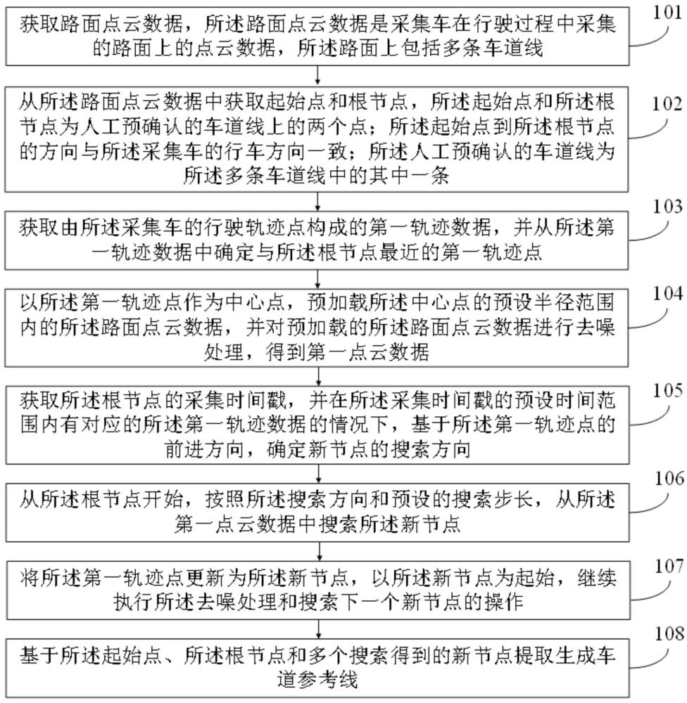



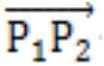
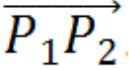
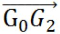
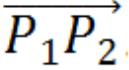
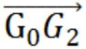
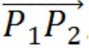
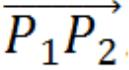
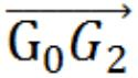
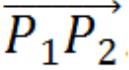
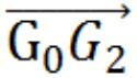
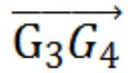
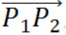

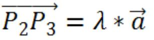
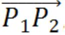
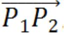

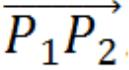

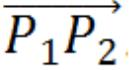

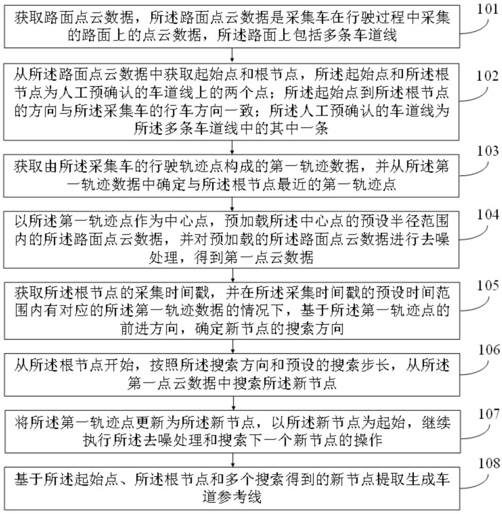
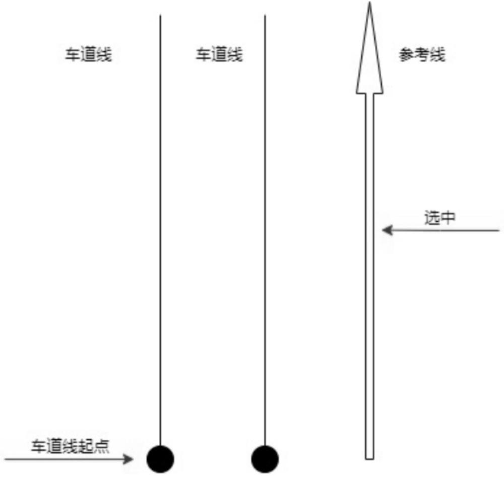
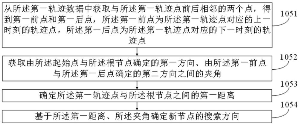
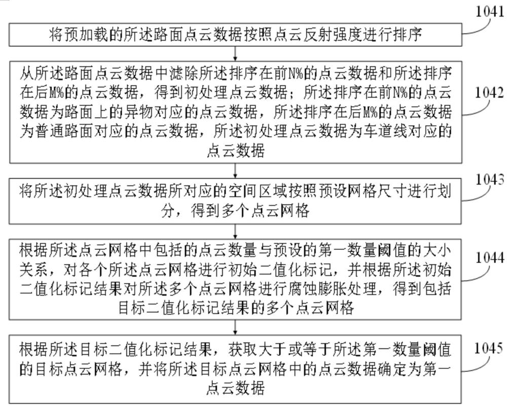
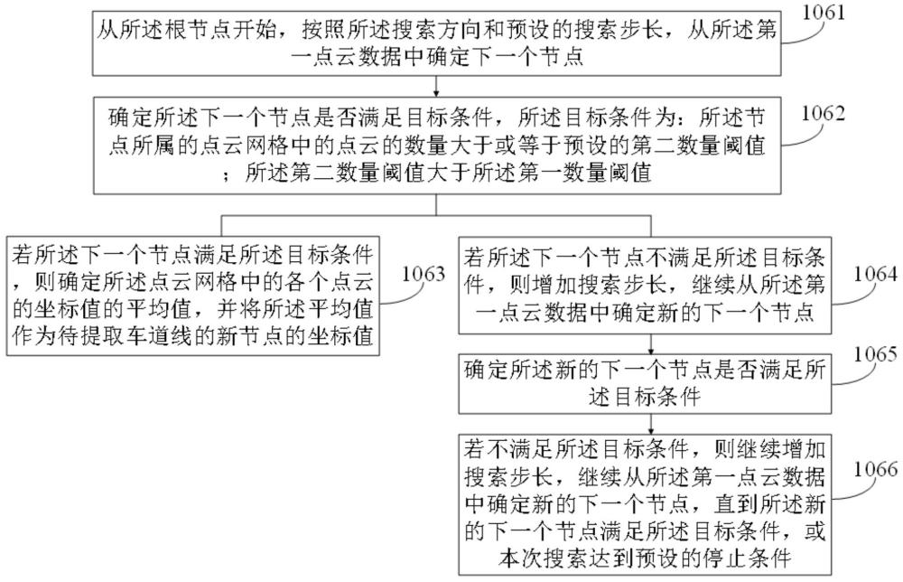
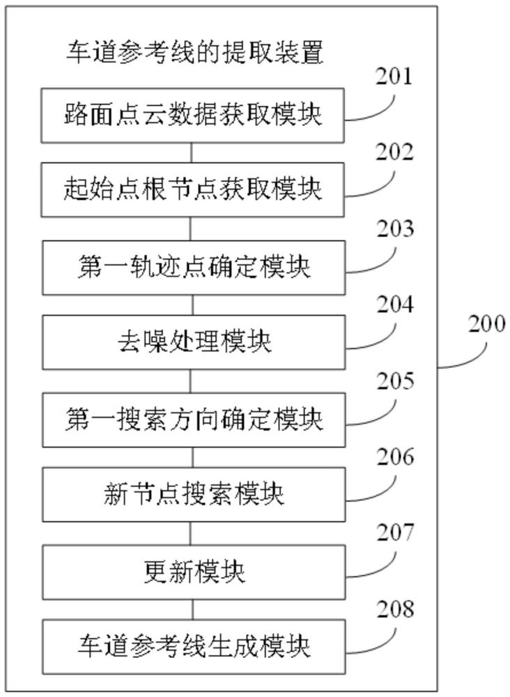




 400-4929-0909
 contact@catarc.com.cn