Technical Field
The utility model belongs to the technical field of hydraulic torque converter tools, and particularly relates to a tool for cleaning and protecting a hydraulic torque converter.
Background Art
In the prior art, the hydraulic torque converter is directly flushed with a hydraulic torque converter, the subsequent hydraulic torque converter is easy to rust, and the risk that a hydraulic torque converter falls off during cleaning is likely to occur.
Content of the utility model
(I) technical problem to be solved
Based on this, the utility model provides a frock for hydraulic torque converter washs protection, this the frock that is used for hydraulic torque converter to wash the protection aims at solving among the prior art washing hydraulic torque converter protection nature is poor. The technical problem of easy falling is solved.
(Two) technical scheme
The tool comprises a connecting plate and a hydraulic torque converter protecting cover arranged on the inner side of the connecting plate, wherein the outer edge of the hydraulic torque converter protecting cover is provided with a clamping sleeve which is protruded along the axial direction of the hydraulic torque converter protecting cover.
, The positioning structure comprises first adjusting blocks detachably installed on the inner side of the upper end of the connecting plate and second adjusting blocks which are detachably mounted on the inner side of the lower end of the connecting plate, and the first adjusting blocks and second adjusting blocks are respectively provided with a plurality of mounting positions along the radial direction of the connecting plate. The upper end and the lower end of the connecting plate can be fixed to a transmission casing corresponding to the hydraulic torque converter through bolts penetrating through the pressing holes respectively; the first adjusting blocks and second adjusting blocks are used for pressing the transmission housing corresponding to the hydraulic torque converter.
, The pressure hole is an elongated hole extending in the radial direction of the connecting plate.
, The positioning structure further comprises a pressing block connected to the inner side of the lower end of the connecting plate through a threaded pull rod, and the pressing block is spaced from the second adjusting block.
, One end of the pressing block along the axial direction of the threaded pull rod is limited by the lug boss, and the pressing block is limited by a nut sleeved on the threaded pull rod along the other end of the threaded pull rod.
, The first adjustment blocks and second adjustment blocks each have a plurality of screws passing through the apertures in the radial direction of the connection plate.
, The outer side of the center of the hydraulic torque converter protecting cover forms a circular truncated cone penetrating through the connecting plate, and the hydraulic torque converter protecting cover forms a circular groove on the inner side of the circular truncated cone.
, The outer side of the connecting plate is connected with a handle.
, The inner side of the hydraulic torque converter protecting cover is further provided with a pressing plate, and the pressing plate, the hydraulic torque converter protecting cover, the connecting plate and the handle are sequentially connected through first screws.
, The connecting plate and the torque converter protecting cover are further connected by second screws.
(Three) benefits
Compared with the prior art, the hydraulic torque converter cleaning protection tool has the beneficial effects that the tool for cleaning and protecting the hydraulic torque converter comprises the following beneficial effects:
The utility model is used in the frock of hydraulic torque converter cleaning protection. An outer edge of the hydraulic torque converter protecting cover is provided with a positioning structure protruded along the axial direction of the hydraulic torque converter protecting cover, and the hydraulic torque converter protecting cover is arranged on the outer circumferential side surface of the hydraulic torque converter protecting cover. The torque converter is prevented from falling off during cleaning.
Description of drawings
The features and advantages of the present invention will become more clearly understood by reference to the accompanying drawings, which are schematic and are not to be construed as limiting the invention in the accompanying drawings.
1 Is a front view of a tool for cleaning and protecting a torque converter according to an embodiment of the present invention.
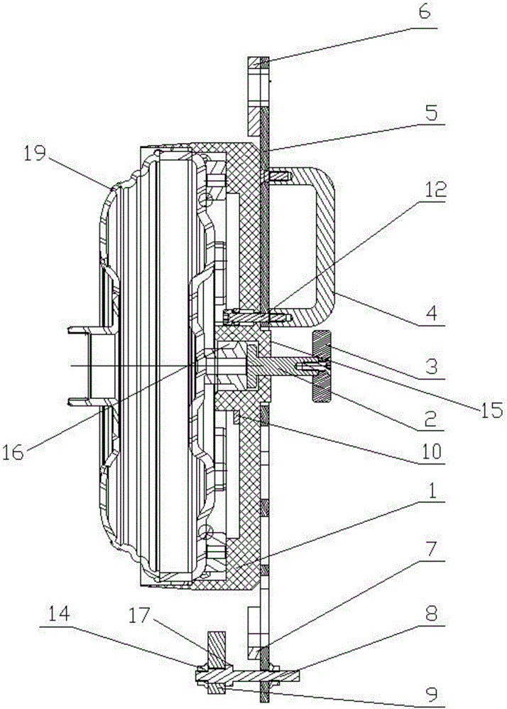
2 Is a cross-section 1-A of FIG. A.
3 Is a perspective view of a tool for cleaning and protecting a torque converter according to an embodiment of the present invention.
Drawings are given in the drawing.
1, The hydraulic torque converter protective cover comprises 2, a top column, 3, a top block, 4, a handle, 5, a connecting plate, 6, first adjusting blocks, 7 and second sets, 8, a threaded rod, 9, 10 screws, 11 nuts, 12, a circular truncated cone, first 15, a circular groove, 16 13, a boss 17, second a press 19 18 hole, 14 and a hydraulic torque converter.
Mode of execution
In order to make the above objects, features and advantages of the present disclosure more comprehensible, specific embodiments of the present invention will be described in detail with reference to the accompanying drawings. In the following description, numerous specific details are set forth in order to provide a thorough understanding of the present invention. The present invention may, however, be embodied in many different forms than those described herein, and it will be apparent to those skilled in the art that similar modifications may be made without departing from the scope of the present invention.
In the description of the present disclosure, unless expressly stated and defined otherwise, the terms' connected, '' connected, 'and' connected ' are to be construed broadly, and may be, for example, fixedly connected, removable, or integrally connected. The utility model can be a mechanical connection or an electric connection, can be directly connected or indirectly connected through an intermediate medium, can be communicated with the inside 2 elements, and can also be a 'transmission connection', that is, through belt transmission. The power connection is carried out in various suitable manners, such as gear transmission or chain wheel transmission. It will be understood by those skilled in the art that the specific meanings of the above terms in the present invention may be specifically understood.
See 1 through 3. The outer edge of the torque converter protection cover 5 is provided with a positioning structure protruding axially along the outer circumferential side surface of the hydraulic torque converter 5, so that the hydraulic torque converter protecting cover 1 is provided with a positioning structure which is fixed to a transmission housing (not shown but well understood) corresponding to the torque converter 1 19 and is also provided with a transmission housing 19 (of course also other housing) corresponding to the torque 19 5 converter 1 in terms of an aspect of the coupling plate 19. To the torque converter 19 installation environment, the installation position is specifically adjusted, and on the other hand, the fixed connection plate 5 also enables the torque converter protection cover 1 to press the torque converter 19 firmly.
To the utility model discloses a specific implementation mode. The positioning structure comprises 5 adjusting blocks first detachably installed inside the upper end of the connecting plate 6 and 5 adjusting blocks second which are detachably mounted on the inner side of the connecting plate 7, and the first adjusting blocks 6 and second are respectively fixed to the transmission housing corresponding to the torque converter 7 through bolts passing through the pressing holes 5.5 and 18 are respectively arranged on the connecting plate 5 for pressing against the transmission housing corresponding to the hydraulic torque converter. The adjusting block 18 and the adjusting block 19 are respectively provided with holes first in the radial direction of the connecting plate. 6 The connecting plates 6 first are respectively provided with adjusting second blocks 7 2nd. 7.5 The adjusting block 19 is provided with a plurality of screw holes. The first adjustment blocks 6 and second adjustment block 7 may be mounted to the connection plate 5 along the radial direction of the connection plate 5 by different screws such that 11 adjustment blocks first and 6 adjustment blocks second may be mounted to the connection plate, so that the 7 adjustment blocks 5 and first adjustment blocks 6 are conveniently ensured to press against the transmission housing corresponding to the torque converter second 19 7. The pressure holes 18 are elongated holes extending radially along the connecting plate 5 such that there are more positions available for the bolts to pass through the elongated holes. The corresponding position of the transmission housing corresponding to the torque converter 19 is fitted in a flexible adjustment position.
Further, the positioning structure further includes a pressing block 8 connected to the inner side of the lower end of the connecting plate 5 through a threaded rod 9, and the pressing block 9 and second adjusting block 7 are spaced so that the briquetting 9 and second adjusting block 7 can clamp the transmission housing corresponding to the torque converter 19.
To a preferred embodiment of the present invention, the threaded rod 8 has a boss 5 at an end inside the lower end of the connecting plate 17, and the pressing block 9 is limited by the boss 8 along the axial end of the threaded rod 17. The pressing block 9 is limited by a nut 8 (for example, a hexagonal flange face nut M6, but not limited to such a nut) fitted to the threaded rod 8 along the other end of the threaded rod 14.
In addition, the outer side of the center of the torque converter protection cover 1 forms a circular groove 5 through which the hydraulic torque converter protection cover 15 is formed, and a top pillar 1 is connected to an end portion inside the circular groove 15 to form a pressure plate, and a top pillar 16 is connected to an inner side (inner side of the circular truncated cone 15) of the hydraulic torque converter protection cover 1 2 by a top block 2 through the top pillar 16 5 on the inner side of the circular cylinder 3.2. The 2 top pillar 15 can be firmly pressed to the axial center side of the 19 hydraulic torque converter 3.
The outer side of the connecting plate 5 is connected with a handle 4, the number 4 of the handles 2 is preferable, but the number is not limited 2.
To the preferred embodiment of the present invention, the inner side of the torque converter protective cover 1 is further provided with a pressing plate 10, a pressing plate 10, a hydraulic torque converter protecting cover 1, a connecting plate 5 and a handle 4 which are sequentially connected through first screws 12 (e.g. hexagonal cylindrical head screws M5 ×3, but not limited to such screws). The connecting plate 5 and the torque converter protecting cover 1 are also connected by second screws 13 (e.g. hexagonal cylindrical head screws M5 ×20, but not limited to such screws), so that the entire tool for hydrodynamic torque converter cleaning protection is more robust.
The tool for cleaning and protecting the hydraulic torque converter according to the embodiment of the utility model is mainly used.
First, the torque converter protecting cover 1 is clamped to the torque converter 19, then 5 adjusting blocks first and 6 of the connecting plate second up and down, and the adjusting block 7 presses the transmission housing corresponding to the torque converter 19. And the briquetting 9 and second adjusting block 7 may clamp the transmission housing corresponding to the torque converter 19, and then install the bolts through respective pressure holes 5 of the upper and lower ends of the connecting plate 18 to corresponding hole positions of the transmission housing corresponding to the torque converter 19, thereby firmly fixing the connecting plate 5 to the transmission housing corresponding to the torque converter 19. The hydraulic torque converter protecting cover 1 protects the surface of the torque converter 19 from being damaged, and on the other hand, the tool for cleaning the hydraulic torque converter is firmly fixed on the transmission housing corresponding to the torque converter 5 through the upper and lower ends of the connecting plate 19. The torque converter 19 is prevented from falling off during cleaning.
While the embodiments of the present invention have been described with reference to the accompanying drawings, those skilled in the art may make various modifications and variations without departing from the spirit and scope of the present invention, all falling within the scope defined by the appended claims.
Tool for cleaning and protecting hydraulic torque converter










 400-4929-0909
 contact@catarc.com.cn