Technical Field
The utility model belongs to the technical field of assembling tools, and particularly relates to an assembling tool for a planetary gear.
Background Art
The planetary gear is an important part of the gearbox, and in the prior art, when the planetary gear is assembled, manual assembly is generally adopted, but a plurality of defects exist in manual assembly: time and labor are wasted. The operation is inconvenient, and the assembly efficiency is low, can't provide high-efficient accurate assembly moreover, takes place quality defect in the assembly process.
Content of the utility model
(I) technical problem to be solved
The utility model provides an assembly fixture for a planet gear, which is used for solving the technical problems of low assembly efficiency and easy quality defects when the planetary gear is assembled in the prior art.
(Two) technical scheme
In order to solve the technical problems, the utility model provides an assembly fixture for a planetary gear, which comprises the following components:
The front end of the pushing mechanism is provided with a planet gear circular arc clamping groove which is concave towards the rear end of the pushing mechanism, and the planet gear circular arc clamping groove is used for limiting matching with the axial protruding circular truncated cone of the planet gear.
, The front end of the upper positioning plate and the front end of the lower positioning plate are respectively provided with the planet gear arc clamping grooves, and the front end of the sliding block forms a concave space for accommodating a tooth part of the planetary gear.
, The sliding blocks are respectively connected with the upper positioning plate and the lower positioning plate through a positioning pin.
, The assembly tool for the planetary gear includes a handle mounted at a rear end of the slider.
, The handle is detachably connected with the slider by a thread.
, The limiting body comprises 2 side beams arranged at intervals and an upper pressing plate and a lower pressing plate connected between 2 side beams, wherein the upper pressing plate is positioned below 2 side beams, the pushing mechanism is limited 2 between the upper pressing plate and the lower pressing plate, and the limiting grooves are arranged on the side beams.
, A cross beam is connected between 2 side beams, and 2 type beam structures are formed between the cross beam and U side beams.
, The side beams are respectively connected with the upper pressing plate and the lower pressing plate through bolts.
, The assembling tool for the planetary gear comprises at least 2 planetary gear arc clamping grooves.
(Three) benefits
Compared with the prior art, the planetary gear assembly tool has the beneficial effects of being used for assembling the planet gears.
The planetary gear circular arc clamping groove is used for limiting and matching with the axial protruding circular truncated cone of the planetary gear, and the planetary gear circular arc clamping groove is used for limiting matching with the axial protruding circular truncated cone of the planetary gear.
Description of drawings
The features and advantages of the present invention will become more clearly understood by reference to the accompanying drawings, which are schematic and are not to be construed as limiting the invention in the accompanying drawings.
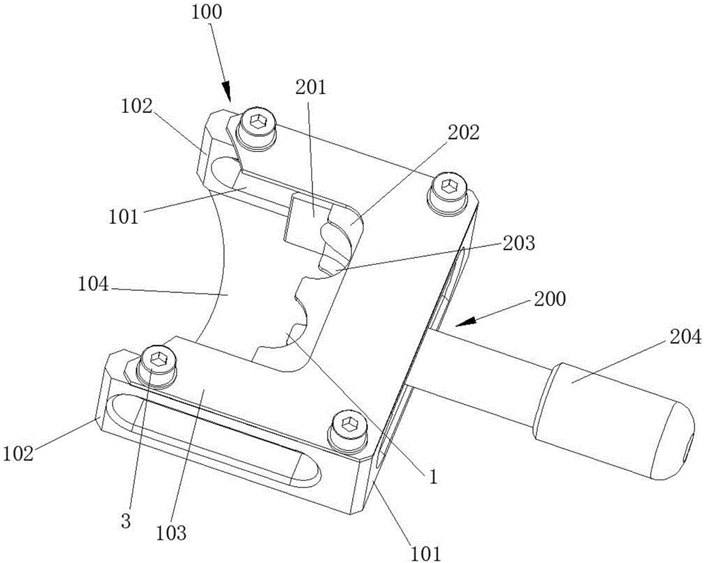
1 Is a perspective view of an assembly tool for a planetary gear according to an embodiment of the present invention.
2 Is a top view of an assembly tool for a planetary gear according to an embodiment of the present invention.
3 Is a side cross-sectional view of an assembly tool for a planetary gear according to an embodiment of the present disclosure.
Drawings are given in the drawing.
1, The planet gears arc clamping grooves, 2, positioning pins, 3, bolts, 100, limiting bodies, 101, limiting grooves, 102, side beams, 103, upper pressing plates, 104, lower pressing plates, 105, cross beams, 200, pushing mechanisms, 201, sliding blocks, 202, upper positioning plates, 203, lower positioning plates, 204 and handles.
Mode of execution
In order to make the above objects, features and advantages of the present disclosure more comprehensible, specific embodiments of the present invention will be described in detail with reference to the accompanying drawings. In the following description, numerous specific details are set forth in order to provide a thorough understanding of the present invention. The present invention may, however, be embodied in many different forms than those described herein, and it will be apparent to those skilled in the art that similar modifications may be made without departing from the scope of the present invention.
In the description of the present disclosure, unless expressly stated and defined otherwise, the terms' connected, '' connected, 'and' connected ' are to be construed broadly, and may be, for example, fixedly connected, removable, or integrally connected. The utility model can be a mechanical connection or an electric connection, can be directly connected or indirectly connected through an intermediate medium, can be communicated with the inside 2 elements, and can also be a 'transmission connection', that is, through belt transmission. The power connection is carried out in various suitable manners, such as gear transmission or chain wheel transmission. It will be understood by those skilled in the art that the specific meanings of the above terms in the present invention may be specifically understood.
To 1 through 3, the utility model provides an assembly fixture for a planetary gear, which comprises the following components:
The limiting body 100 is slidably installed on the pushing mechanism 100 of the limiting body 200, and the front end of the pushing mechanism 200 is provided with a planet gear circular arc clamping groove 200 which is concave towards the rear end of the planetary gear, and the planet gear circular arc clamping groove 1 1 is used for limiting matching with the axial protruding circular truncated cone of the planet gear and then pushing the pushing mechanism 200 1 forward.
To the utility model discloses a specific implementation mode. The advancing mechanism 200 comprises a slider 201, an upper positioning plate 201 mounted above the slider 202, and a lower positioning plate 201 mounted below the slider 203, and the front ends of the sliders 100 are respectively slidably clamped in the corresponding limiting grooves 101, and the front ends of the sliders 201 201 203 are respectively provided with concave spaces for accommodating the teeth portions of the planetary gears and the upper positioning plate 101 and 1 the lower positioning plate 202. , The planet gear arc clamping grooves 202 of the upper positioning plate 1 and and the lower positioning plate 203 1 are respectively and limited in cooperation with the axial protruding circular truncated cones at the upper and lower ends.
To the utility model discloses a specific implementation mode. The slider 201 is connected with the upper positioning plate 202 and the lower positioning plate 203 through a positioning pin 2, respectively. The assembly tool for the planetary gear includes a handle 201 mounted to a rear end of the slider 204. The specific handle 204 is detachably connected to the slider 201 by a screw. The limiting body 100 comprises 2 side beams 102 arranged at intervals and the upper and lower pressing plates 2 and 102 connected between 103 side beams 104, and the upper pressing plate 103 is positioned below 2 side beams 102, and the pushing mechanism 200 104 is limited between the upper pressing plate 103 2 and the lower pressing 104 plate 102. A spacing groove 101 is provided on the side sill 102. Between 2 side beams 102, a cross member 105 is connected, and the beam 105 and 2 side beams 102 form U-type beam structures. The side beams 102 are respectively connected to the upper platen 103 and the lower platen 104 by bolts 3. The assembling tool for the planetary gear comprises at least 2 planetary gear arc clamping grooves 1. Of course, the specific structural design and the number design are obviously not limited to this, and the adjustment can be flexibly changed according to practical needs.
While the embodiments of the present invention have been described with reference to the accompanying drawings, those skilled in the art may make various modifications and variations without departing from the spirit and scope of the present invention, all falling within the scope defined by the appended claims.
Assembly tool for planetary gear










 400-4929-0909
 contact@catarc.com.cn