Contents of the Invention
Object of the present invention is to provide a rear tie rod test system to solve the prior art, the rear tie rod test can not simulate the real force and motion attitude, resulting in the test is not accurate enough technical problems.
To achieve the above object, the technical solution employed in the present invention is:
To provide a rear plunger test system for testing the rear plunger rod, the rear vertical rod comprises a rod body, a ball pin located at one end of the rod body and a bushing located at the other end of the rod body, wherein comprising:
Ball pin loading clamping fixture for fixing the ball pin;
Single-axis loading clamping fixture for fixing the bushing;
First linear loading module for loading the linear load in the first direction to the ball pin loading clamping fixture;
Second linear loading module for loading the linear load in the second direction to the ball pin loading clamping fixture;
Loading constraint module, including a load constraint mechanism with an axis direction in the third direction, the end rotation of the loading constraint mechanism is mounted on the ball pin loading clamping fixture;
Torsional loading module for loading torsional loads into the uniaxial loading clamping fixture.
Further, the first direction, the second direction, the third direction between the two two perpendicular to each other.
Further, the spherical pin loading clamping fixture comprises a multi-axis loading clamping frame, the multi-axis loading clamping frame is provided with a cavity for insertion of the spherical pin into the fixed cavity;
The first linear loading module, the second linear loading module, and the loading constraint module are connected to the multi-axis loading clamping frame.
Further, the multiaxial loading clamping frame is provided with a first connecting ear and a second connecting ear perpendicular to each other;
The first connection ear is installed with a first loading connector, the first connection outside the ear rotation is installed with a loading restraint head; The second connection is installed inside the ear with a second loading connector;
The first linear loading module is connected to the first loading connector, the second linear loading module is connected to the second loading connector, the loading constraint mechanism is connected to the loading constraint header.
Further, the loading constraint head is a spherical type rotating connection structure.
Further, the first linear loading module comprises a first servo electric cylinder and a first loading connection mechanism, one end of the first loading connection mechanism is connected to the output of the first servo motor, the other end of the first loading connection mechanism is connected to the first loading connector.
Further, the second linear loading module comprises a second servo electric cylinder and a second loading connection mechanism, one end of the second loading connection mechanism is connected to the output of the second servo motor, the other end of the second loading connection mechanism is connected to the second loading connector.
Further, the first connecting ear having a first mounting hole, the loading restraint head comprises a constraint screw provided through the first mounting hole and a constraint nut for fixing the constraint screw, the end of the first loading connector is provided with a spherical bearing set on the restraint screw.
Further, the single-axis loading clamping fixture comprises a substrate and two mounting arms mounted on the substrate, the bushing inserted between the two mounting arms for fixation; The plane on which the substrate is located is parallel to the rod body, the torsional loading module is connected to the substrate.
Further, the torsional loading module comprises a sequentially connected servo motor, a reducer, coupling, torque sensor, angle sensor and transmission mechanism, the transmission mechanism is connected to the substrate.
Further, the rear vertical rod test system further comprises an environmental box, the environmental box comprising a box, a temperature and humidity control module, a mud injection control module, an ozone aging action module.
Further, the post-vertical lever test system further comprises a host computer and a controller connected to the host computer, the controller is connected to the environment box, the first linear loading module, the second linear loading module, the torsional loading module.
Advantageous effects of the post-tie rod test system provided by the present invention are:
Using the rear vertical tie rod test system of the present invention, the linear load is loaded backwards by the first linear loading module or the second linear loading module to the rear vertical pull rod, and other degrees of freedom are limited by the loading constraint module, a one-way load test may be performed; It can also be loaded with different types of loads in different directions through the first linear loading module, the second linear loading module and the torsional loading module, and other degrees of freedom are restricted by the loading constraint module to carry out multi-axis periodic or random load spectrum loading, so that the test can cover the load spectrum loading from single axis to multi-axis, and switch freely according to actual needs, so as to realize the periodic load signal test equivalent to road test or damage, and the test can realistically simulate the force and motion attitude of the rear vertical tie rod in the real car. It can quickly assess the rear tie rod bushing and rod structure, which improves the accuracy of the test on the basis of improving the test efficiency.
Specific embodiments
In order to solve the technical problems of the present invention, technical solutions and beneficial effects more clearly understood, the following in conjunction with the accompanying drawings and embodiments, the present invention will be further elaborated in detail. It should be understood that the specific embodiments described herein are merely used to explain the present invention and are not intended to qualify the present invention.
It should be noted that when a component is said to be "fixed to" or "set to" another component, it can be directly on another component or indirectly on that other component. When a component is said to be "connected to" another component, it can be either directly connected to another component or indirectly connected to the other component.
It should be understood that the term "length", "width", "up", "down", "front", "back", "left", "right", "vertical", "horizontal", "top", "bottom" and other indications of the orientation or position relationship is based on the orientation or position relationship shown in the accompanying drawings, only to facilitate the description of the present invention and simplified description, rather than indicating or implying that the means or elements referred to must have a specific orientation, structured and operated in a particular orientation, and therefore cannot be understood as a limitation of the present invention.
Further, the terms "first", "second" are for descriptive purposes only and cannot be construed as indicating or implying relative importance or implicitly indicating the number of technical features indicated. Thus, the features limited to "first" and "second" may explicitly or implicitly include one or more of the features. In the description of the present invention, "multiple" means two or more, unless otherwise expressly specifically qualified.
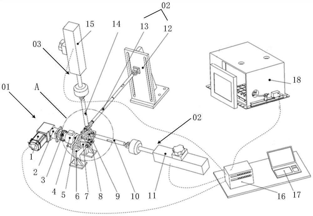
Referring to FIGS. 1 to 8, the rear tie rod test system provided in an embodiment of the present invention is described, the rear tie rod test system for testing the post tie rod 8. Rear tie rod 8 comprises a club body, with a pin 81 at one end of the club and a bushing 82 at the other end of the club.
The rear vertical rod test system specifically includes: ball pin loading clamping fixture 9, single-axis loading clamping fixture 7, first linear loading module 02, second linear loading module 03, loading constraint module and torsional loading module 01. Wherein, the ball pin loading clamping fixture 9 is used to fix the ball pin 81, the single-axis loading clamping fixture 7 is used to fix the bushing 82, the ball pin loading clamping fixture 9 and the single-axis loading clamping fixture 7 are combined to form a special tooling for fixing the rear vertical tie rod 8.
The first linear loading module 02 is used to load the clamping fixture to the ball pin 9 to load the linear load in the first direction, the second linear loading module 03 is used to load the clamping fixture to the ball pin 9 to load the second direction linear load; Loading constraint module includes a load restraint mechanism 13 with an axis direction in the third direction, the end rotation of the loading restraint mechanism 13 is mounted on the ball pin loading clamping fixture 9.
Torsional loading module 01 is used to load torsional loads to a single-axis loading clamping fixture 7.
Before using the rear vertical rod test system in the present embodiment of the rear vertical rod 8, the rear vertical rod 8 is loaded into a special tooling, the ball pin 81 is also fixed to the ball pin loading clamping fixture 9, and the bushing 82 is fixed to the uniaxial loading clamping fixture 7. At this time, the load may be applied by the first linear loading module 02, the second linear loading module 03 to the rear vertical tie rod 8 to apply two straight direction loads, and by torsional loading module 01 load to load the torsional load, and while applying the load, by the loading constraint mechanism 13 limits the non-target direction of movement of the rear vertical tie rod 8, to constrain the excess freedom of the rear vertical tie rod 8, by setting the type and time of the load, you can test the rear vertical tie rod 8, and can increase the adaptation environment box 18, providing the temperature and humidity required for the sample, mud, Environmental conditions such as aging.
The rear tie rod test system can perform single-axis load tests or multiple shaft load tests:
(1) The rear vertical tie rod test system can carry out a single-axis loading test, that is, only through the first linear loading module 02 or the second linear loading module 03 to load the straight line load backward vertical rod 8, other load modules are not involved in the test, and the loading constraint module limits other degrees of freedom, to achieve a one-way application of linear load, in order to test the load in the one-way force state as needed. Alternatively, the first linear loading module 02 or the second linear loading module 03 does not participate in the test, the load is applied by the torsional loading module 01, the load situation in the one-way torsional state is tested.
(2) The rear vertical tie rod test system can also carry out multi-axis loading test, that is, the first linear loading module 02, the second linear loading module 03 and the torsional loading module 01 are all involved in the test, and at the same time or according to the time interval, the rear vertical rod 8 is applied to continuous load, periodic load or random load that changes with the time law, and the load constraint module limits other degrees of freedom, simulating the complex load situation in the actual driving state according to the test requirements.
Therefore, the use of the rear vertical tie rod test system in the present embodiment can be targeted single axial load test, can also be multi-axis random load spectrum loading, can be carried out periodic load signal or random load spectrum iterative signal loading, to achieve road simulation test or damage equivalent to the road test of the periodic load signal test, can truly simulate the real car in the rear vertical rod 8 sample force and motion attitude, can be the rear vertical rod 8 bushing 82 and rod structure for rapid assessment, in the early stage of development or for the problem to verify , save the development cycle, on the basis of improving the test efficiency, improve the accuracy of the test. The test of the rear tie rod test system can cover single-axis to three-axis loading, and can be switched freely according to actual needs, with the characteristics of accurate test reproduction and good repeatability.
Alternatively, the first direction, the second direction, and the third direction are two perpendicular to each other, forming three coordinate directions in the Rectangular Coordinate System, in order to simulate the actual force load direction of the rear vertical tie rod 8, and the simulated loading test of the three-axis decoupling of the rear vertical tie rod 8 can be realized.
Optionally, as shown in FIGS. 4 and 5, the ball pin loading clamping fixture 9 in the present embodiment includes a multi-axis loading clamping frame 91, the multi-axis loading clamping frame 91 is provided with a cavity for the ball pin 81 to be inserted into a fixed cavity, the first linear loading module 02, the second linear loading module 03 and the loading constraint module are connected to the multi-axis loading clamping frame 91. After the ball pin 81 of the rear vertical lever 81 is inserted into the cavity of the multi-axis loading clamping frame 91, it is fixed with the multi-axis loading clamping frame 91, because the ball pin 81 is inserted into the interior of the multi-axis loading clamping frame 91, so the load received by the multi-axis loading clamping frame 91 can be uniformly transmitted to the ball pin 81, to achieve the role of fixing and transmitting load and motion.
Optionally, as shown in FIGS. 4 and 5, the side of the multi-axis loading clamping frame 91 is provided with an opening connected to its cavity, the spherical pin loading clamping fixture 9 further comprises a press-fit cover plate 93, a plurality of ring tube pads 92 and a plurality of fastening bolts 94. The press-fit cover plate 93 has a center hole, the spherical pin 81 is inserted into the cavity after being installed in place directly opposite the center hole. From the center hole into the threaded shaft of the spherical pin 81, through the opening into the cavity and inserted into the spherical pin 81 for positioning. There are multiple locking holes around the compression cover plate 93, the two fastening bolts 94 provided below sequentially pass through the locking hole on the compression cover plate 93, the ring tube pad 92, the end of the two fastening bolts 94 passes through the through hole on the multi-axis loading clamping frame 91 and locks through the nut, the two fastening screws 95 set above through the compression cover plate 93 are directly screwed into the threaded hole on the multi-axis loading clamping frame 91, and together they lock the ball pin 81 thread shaft and the pressed cover plate 93, and finally realize the clamping fixation of the ball pin 81 structure , can meet the requirements of not loosening in the fatigue test, improve the accuracy of test reproduction.
Alternatively, as shown in FIGS. 4 and 5, the multiaxial loading bracket 91 in the present embodiment is an overall quadriposic shape, and the two adjacent sides of the multiaxial loading clamping frame 91 are provided with a first connecting ear 911 and a second connecting ear 912, respectively, the first connecting ear 911 and the second connecting ear 912 are perpendicular to each other. In the first connection 911 is installed with a first loading connector 971, the first connection ear 911 is installed with a loading restraint head 96, in the second connection branch 912 is installed with a second loading connector 972, the first loading connector 971, the second loading connector 972 and the loading restraint head 96 are two perpendicular to each other. The first linear loading module 02 is connected to the first loading connector 971, the second linear loading module 03 is connected to the second loading connector 972, the loading constraint mechanism 13 is connected to the loading constraint head 96, and the load applied to the multi-axis loading clamping frame 91 is jointly tested. Among them, the dimensions of the multi-axis loading clamping frame 91 can be specially designed according to the size of the ball pin 81 to ensure the accuracy of the fit.
Optionally, as shown in FIGS. 4 and 5, the loading restraint head 96 in the present embodiment is a spherical type rotating connection structure, when the position of the multi-axis loading clamping frame 91 is loaded, the spherical type rotating connection structure can be rotated and tilted but cannot be detached, and the constraint freedom in the direction of the 13 axis of the loading restraint mechanism can still be guaranteed, limiting the non-target motion of the rear vertical pull rod 8, and also preventing the rear vertical pull rod 8 from being affected by additional torque. The spherical type rotating connection structure can be realized by the universal joint, spherical joint, spherical bearing and other structures, which will not be repeated. Multi-axis loading clamp frame 91 connection support installation loading connector 97, loading connector 97 select standard rod end bearing, can be rotated around the connecting bolt axis, the mounting bolt axis of the connecting ear is vertical design, according to the direction of the loading movement to select the opening direction of the corresponding connection of the support to ensure that the movement is not interfering, so that the load is applied accurately, the threaded shaft part of the loading connector 97 is connected with the loading connection mechanism of the first linear loading module 02 and the second linear loading module 03.
Optionally, as shown in FIGS. 4 and FIG. 5, the first connection ear 911 has a first mounting hole, the loading restraint head 96 includes a restraint screw provided through the first mounting hole and a restraint nut for fixing the constraint screw, the first loading connector 971 is provided with a spherical bearing mounted on the restraint screw. The restraint screw and the restraint nut are fixed on the first connection ear 911, so that the loading restraint head 96 is fixed, at the same time, the joint bearing at the end of the first loading connector 971 is set on the restraint screw to achieve the fixation of the first connection ear 911, and to ensure that the loading restraint head 96 and the first loading connector 971 are perpendicular to each other. The axis of the constraint screw is designed vertically, and the opening direction of the corresponding connecting ear is selected according to the direction of the loading motion to ensure that the movement is not interfered with, so that the load is applied accurately. The spherical bearings set at the end of the first loading connector 971 can still ensure that the first loading connector 971 and the multi-axis loading clamping frame 91 are connected and fixed to ensure that the maximum range of movement of the rear vertical tie rod 8 is non-interference- when the multi-axis loading clamping frame 91 is moved after the load is loaded, and the additional directional force and torque are eliminated. In the present embodiment, the second loading connector 972 and the second connection ear 912 fixing method, and the first loading connector 971 is similar to the fixing method, the same set corresponding to the fixing of the second connection ear 912 screw, nut, and then by the way of the spherical bearing sleeve on the screw and the second connection ear 912 fixed connection, the same technical effect. In other embodiments, the second loading connector 972 may also employ other fixing methods, e.g., through the spherical joint and the second connection ear 912 fixation and the like.
Optionally, as shown in FIGS. 1 to 4, the single-axis loading clamping fixture 7 in the present embodiment comprises a substrate 71 and a two mounting arms 72 mounted on the substrate 71, the bushing 82 is inserted between the two mounting arms 72 for fixing; The plane where the substrate 71 is located parallel to the rod body, that is, the vertical plane in the diagram, the torsional loading module 01 is connected to the substrate 71. Substrate 71 carries the torsional load after rotating in the vertical plane, through the mounting arm 72 the torsional load is transmitted to the bushing 82. Single-shaft loading clamping fixture 7 is a universal fixture tool developed for bushing 82, generalized ball pin loading clamping fixture 9 is specially designed according to the ball pin structure, no need to remove the injection molding of the integrated ball pin 81 seats, to avoid destroying the structure of the rear vertical tie rod 8 samples, to ensure that the test results are not affected, and to meet the test clamping does not loosen and installation and disassembly convenient requirements, and suitable for different models of rear vertical rod 8 size, the distance and length of the mounting arm 72, can be designed as needed to meet different rear vertical rod 8 tests.
Alternatively, as shown in FIG. 6, the torsional loading module 01 in the present embodiment includes a service motor 1, a reducer 2, a coupling 3, a torque sensor 4, an angle sensor 5 and a transmission mechanism, the transmission mechanism is connected to the substrate 71. The servo motor 1 is connected to the reducer 2 by means of a square flange, and the torque transducer 4 is connected to the reducer 2 by coupling 3 and is fixed to the table together. Servo motor 1, torque sensor 4 and angle sensor 5 constitute a closed-loop control mode to accurately realize the swing or torsional loading motion of the rear vertical tie rod 8. Servo motor 1 output torque, deceleration by the reducer 2 output to the substrate 71 through the coupling 3, and through the torque sensor 4 to detect the torque, through the angle sensor 5 to obtain the angle of rotation, the relationship between the two can obtain the force deformation of the rear vertical lever 8, so that the user according to the detection data to adjust the torsional load to meet the test needs. In other embodiments, the hydraulic torsional actuator may also be substituted for the servo motor 1 to achieve torque output.
Alternatively, the torsional loading module 01 in the present embodiment further comprises a transmission support mechanism 6, the transmission support mechanism 6 itself is a bracket structure, the transmission support mechanism 6 is opened with a mounting hole, the torque sensor 4 is connected to the transmission support mechanism 6 by spline, the transmission support mechanism 6 is connected to the mounting clamping module by means of a transmission mechanism (e.g., rotating the connection plate), specifically connected to the substrate 71 in the present embodiment. The lower end of the transmission support mechanism 6 is equipped with a foot, which is mounted on the table to achieve support and fixation of the entire single-shaft loaded clamping fixture 7. In the present embodiment, the transmission mechanism is a rotating connection disc is only an exemplary illustration, in other embodiments, the transmission mechanism may also be a flange, or a bolt.
Alternatively, as shown in FIGS. 1 and 7, the first linear loading module 02 in the present embodiment comprises a first servo-electric cylinder 11 and a first loading connection mechanism 10, one end of the first loading connection mechanism 10 is connected to the output end of the first servo electric cylinder 11, the other end of the first loading connection mechanism 10 is connected to the first loading connector 971, the linear load is output by the first servo electric cylinder 11, through the first loading connection mechanism 10, the first loading connector 971 is finally transmitted to the ball pin 81 of the rear vertical rod 8. The connecting rod in the first loading connection mechanism 10 is a loading force transmission structure, and the connecting rod is set according to the range of motion of the mounting clamping module to reduce the influence of the swing angle.
Alternatively, as shown in FIGS. 1 and 7, the second linear loading module 03 in the present embodiment may be identical to the structure of the first linear loading module 02, i.e., the second linear loading module 03 comprises a second servo electric cylinder 15 and a second loading connection mechanism 14, one end of the second loading connection mechanism 14 is connected to the output end of the second servo electric cylinder 15, the other end of the second loading connection mechanism 14 is connected to the second loading connector 972, the linear load is output by the second servo electric cylinder 15, By a second loading connection mechanism 14, the second loading connector 972 is finally transmitted to the rear vertical lever 8. In other embodiments, the first linear loading module 02 may also be employed in the structure of the cylinder, linear motor and the like to achieve the function of the first linear loading module 02, the first linear loading module 02 and the second linear loading module 03 may employ different structures.
Optionally, as shown in FIGS. 1 and 8, the loading constraint module in the present embodiment includes a fixed column 12 mounted on the table and a load constraint mechanism 13 rotating connected to the fixed column 12, the loading constraint mechanism 13 is connected to the loading restraint head 96 with the fixed column 12, limiting the movement of the vertical rod 8 in the non-target direction after the vertical tie rod. Loading the binding mechanism 13 of the connecting rod is a small diameter lightweight member, the length is set as long as possible, the constraint excess degrees of freedom.
Optionally, as shown in FIG. 1, the rear vertical rod test system in the present embodiment further comprises an environmental box 18, an environmental box 18 comprising a cabinet, a temperature and humidity control module, a mud injection control module, an ozone aging module, and an observation window is provided on the box. The aforementioned ball pin loading clamping fixture 9, single-axis loading clamping fixture 7 and rear vertical rod 8 structure are placed in the box body, and a plurality of connection holes are opened on the box for the relevant connecting rods, cables, etc. to pass through. Through the environment box 18 in the temperature and humidity control module, mud injection control module, ozone aging module to simulate temperature, humidity, mud injection, ozone and other environments, you can simulate the bushing 82 periodic aging treatment, slurry jetting and other working conditions, simulating the real use environment and the use cycle, further improve the realism of the environmental simulation, in a more realistic environment after testing the vertical tie rod 8, to ensure the accuracy of the test.
Alternatively, as shown in FIG. 1, the rear vertical rod test system in the present embodiment further comprises a host computer 17 and a controller 16 connected to the host computer 17, the controller 16 is connected to the environment box 18, the first linear loading module 02, the second linear loading module 03, the torsional loading module 01. Analog loading execution system, controller 16, host computer 17 through the signal line to establish a connection, in order to carry out real-time test feedback and control. Run the corresponding test program in the host computer 17, determine the load loading scheme during the test, and output instructions to the controller 16, the controller 16 in the control environment box 18, the first linear loading module 02, the second linear loading module 03, the torsional loading module 01 synchronously receive the data of each module, to achieve closed-loop testing, more automated and intelligent completion of the entire test process.
Using the rear tie rod test system in the present embodiment, the test process of the rear tie rod 8 is:
Determine the test scheme, the test scheme includes the test environment (specifically including temperature, humidity, mud, ozone), the number of loads (single-axis or multi-axis loads), each load type (continuous, time-based fluctuations, random), etc., and in the host computer 17 control interface to complete the control program after the completion of the control program is sent to the controller 16 to achieve the loading module target drive sent to the controller 16. The upper end of the rear vertical tie rod 8 is inserted into the interior of the multi-axis loading clamping frame 91 so that the ball pin 81 and the multi-axis loading clamping frame 91 are fixed to each other, and the lower end of the rear vertical rod 8 is inserted between the two mounting arms 72 on the substrate 71 so that the bushing and the substrate 71 are fixed to each other. The environmental box 18 receives data from the controller 16 to simulate a particular environment.
The first linear loading module 02 controls the first servo electric cylinder 11 according to the instructions of the controller 16 to output the corresponding linear load signal, and through the loading connection mechanism to achieve the rear vertical tie rod 8 in the ball pin 81 end center around the bushing 82 axis swing to the target angle, the rear vertical tie rod 8 bushing 82 end by a single shaft loading clamping fixture 7 clamping, the metal inner tube of the bushing 82 rotates the axis; The second linear loading module 03 outputs the corresponding load signal according to the instructions, and realizes the target load in the direction of the rod body by loading the connection mechanism, the bushing 82 end of the rear vertical tie rod 8 is clamped by a single-axis loading clamping fixture 7, the metal inner tube of the bushing 82 is translated when the tensioning action is carried out, and the loading constraint module is connected to the installation clamping module by loading the restraint mechanism 13, and the loading restraint head 96 limits the lateral movement of the rear vertical pull rod 8, Ensure that the longitudinal motion load and vertical load act accurately on the assessment site of the rear vertical tie rod 8; In addition, the ball pin loading clamping fixture 9 is a special design tooling, with the loading connection mechanism in the connection rod and the constraint rod in the loading constraint mechanism 13, to ensure that the linear loading movement or the applied load is not coupled, the load effect is precise, and finally realize the multi-axis road simulation loading test of the bushing 82 and the rod structure and other assessment parts.
Torsional loading module 01 according to the controller 16 instructions control servo motor 1 output corresponding rotation or swing signal, drive the connected installation clamping module in the rear vertical rod 8 bushing 82 ends to twist to the target load or angle, while loading constraint module connected to the installation clamping module in the rear vertical rod 8 of the ball pin 81 end, in order to limit the lateral movement of the rear vertical tie rod 8, to ensure that the torsional load accurately acts on the rear vertical rod 8 bushing 82 and the rod structure and other assessment parts.
The above detection process can be switched between single-axis load and multi-axis load, and added environmental influence factors, can simulate the actual force situation and motion conditions of the rear vertical rod 8, in order to find problems in the test process as early as possible, in order to test and verify in the early stage of development or for problems, saving the development cycle, improving test efficiency and accuracy.
The above system can also be extended to multi-axis assessment of other structural parts to improve the structural testing capabilities of parts. Combined with the environmental box 18 to provide the temperature and humidity required after the tie rod 8, mud, aging and other environmental conditions on the rubber bushing 82 or other plastic structure assessment, and a comprehensive evaluation.
The above system drives the servo electric cylinder or servo motor 1 according to the control module, adapts to the corresponding load sensor to complete the closed-loop control, has a random load signal control loading mode, designs and connects the tooling and installs the fixed modules, the system cost is low, the development cycle is short, and the maintenance is simple.
The above is only a better embodiment of the present invention, and is not intended to limit the present invention, where any modifications, equivalent substitutions and improvements made within the spirit and principles of the present invention, etc., should be included within the scope of the present invention.


 400-4929-0909
 contact@catarc.com.cn

