Contents of the invention
An object of the present invention is to provide an uninterruptible power supply system based on supercapacitor, adopt supercapacitor instead of storage battery as energy storage unit, effectively improve the deficiency of traditional uninterruptible power supply, greatly improve the performance of uninterruptible power supply.
First, the invention provides an uninterruptible power supply system based on a supercapacitor, comprising a power supply circuit and a microcontrol unit, the power supply circuit is connected with the microcontrol unit and is used for supplying power to the microcontrol unit, and further comprises:
the supercapacitor group is connected to the power supply circuit and is provided with a switch between the supercapacitor group and the power supply circuit;
the input end of the supercapacitor control circuit is connected with the microcontrol unit and the output end is connected with the switch; the supercapacitor control circuit is used for receiving the signal sent by the microcontrol unit to control the switch to close or disconnect.
The uninterruptible power supply system based on supercapacitor provided by the present invention can better overcome the shortcomings of the uninterruptible power supply that traditional battery is used as an energy storage unit, and the effect of improving the performance of uninterruptible power supply is achieved.
further comprising a first buck-boost circuit, wherein the first buck-boost circuit is arranged on the power supply circuit, the input end of the first buck-boost circuit is connected with the power supply, and the output end is electrically connected with the microcontrol unit;
The output end of the first buck-boost circuit is further connected with the input end of the supercapacitor group through a power supply branch bifurcated from the power supply circuit.
By setting up the first buck-boost circuit, the uninterruptible power supply system can be used with a variety of power supplies, and the applicability of the uninterruptible power supply system is greatly improved.
Further, a first diode is arranged between the output end of the first buck-boost circuit and the bifurcation of the power supply circuit; the first diode is used for preventing the current from being backfilled into the first buck-boost circuit.
The first diode prevents the current from flowing into the power supply when the supercapacitor bank is discharged, causing the power supply to burn out.
further comprise a second buck-boost circuit, the second buck-boost circuit is arranged on the power supply circuit and is located between the bifurcation of the power supply circuit and the microcontrol unit, the input end of the second buck-boost circuit is electrically connected with the output end of the first buck-boost circuit and the output end is connected with the microcontrol unit;
The output end of the supercapacitor group is connected with the second buck-boost circuit through the switch.
By setting up the second buck-boost circuit, the uninterruptible power supply system can be used with a variety of microcontrol units, and the applicability of the uninterruptible power supply system is further improved.
Further, a second diode is arranged between the output end of the supercapacitor group and the switch, and the second diode is used for preventing the current from being poured into the supercapacitor group.
Furthermore, a first resistor is arranged between the input end of the supercapacitor group and the power supply circuit, and the first resistor is used for limiting the current flowing into the supercapacitor group so that the supercapacitor group can be charged in a constant current state.
Further, the supercapacitor group comprises one supercapacitor.
Further, the supercapacitor group comprises a plurality of supercapacitors, the supercapacitors are divided into a plurality of blocks, each of which comprises at least one supercapacitor and the adjacent two blocks are connected in parallel with each other.
Further, each block comprises a plurality of supercapacitors, and a plurality of supercapacitors in the same block are connected in series with each other.
Further, each supercapacitor is connected with a corresponding second resistor.
It can be seen from the above that in the uninterruptible power supply system based on supercapacitor of the present invention, because the supercapacitor not only has the charge energy storage function that the traditional chemical battery should have, but also has excellent discharge performance, such as large capacity, high energy conversion efficiency, strong anti-interference ability, allowable high-current charging and discharging, etc., therefore the supercapacitor is more stable and reliable than the traditional battery, and the supercapacitor replaces the battery as the energy storage unit of the uninterruptible power supply, and can greatly improve the performance of the uninterruptible power supply.
Other features and advantages of the present invention will be described in a subsequent description and, in part, become apparent from the description or become known by the embodiment of the present invention. The object and other advantages of the present invention may be realized and obtained by means of the structure specified in the written description and in the accompanying drawings.
The specific embodiment
An embodiment of the present invention is described in detail below, and examples of said embodiments are shown in the drawings where the same or similar designations from beginning to end indicate the same or similar elements or elements having the same or similar functions. The embodiments described below by reference to the drawings are illustrative and are intended to explain the invention only and should not be construed as limiting the invention.
In the description of the present invention, it is necessary to understand that the terms "center", "longitudinal", "transverse", "length", "width", "thickness", "up", "down", "front", "back", "left", "right", "vertical", "horizontal", "top", "bottom", "inside", "outside", "clockwise", "counterclockwise" The orientation or positional relationship indicated is based on the orientation or positional relationship shown in the drawings, and is only for the convenience of describing the present invention and simplifying the description, and does not indicate or imply that the device or element referred to must have a specific orientation, be constructed and operated in a specific orientation, and therefore cannot be construed as a limitation on the present invention. In addition, the terms "first" and "second" are used for descriptive purposes only and should not be construed as indicating or implying relative importance or implying the number of technical features indicated. Thus, the features that are defined as "first" and "second" may explicitly or implicitly include one or more of the features described. In the description of the present invention, "plurality" means two or more of them, unless otherwise expressly and specifically qualified.
In the description of the present invention, it should be noted that, unless otherwise expressly specified or limited, the terms "mounted", "connected" and "connected" shall be understood broadly, for example, they may be fixed, detachable, or integrally connected, mechanically connected, electrically connected or can communicate with each other, they may be directly connected or indirectly connected through an intermediate medium, and they may be connected internally or interacted between two elements. For a person of ordinary skill in the art, the specific meaning of the above terms in the present invention may be understood according to the specific circumstances.
In the present invention, unless otherwise expressly specified or qualified, the first feature "above" or "below" the second feature may include direct contact between the first and second features, or the first and second features are not in direct contact but through additional feature contact between them. Moreover, the first feature is "above", "above", and "above" the second feature includes the first feature directly above and obliquely above the second feature, or simply indicates that the first feature is horizontally higher than the second feature. The first feature is "below", "below", and "below" the second feature, including the first feature directly below and diagonally below the second feature, or simply indicating that the horizontal height of the first feature is less than that of the second feature.
The following disclosure provides a number of different embodiments or examples for the different structures used to realize the invention. In order to simplify the disclosure of the present invention, the parts and settings of a particular example are described below. Of course, they are only examples and are not intended to limit the invention. In addition, the present invention may repeat reference numbers and/or reference letters in different examples, and such repetition is for the purpose of simplification and clarity, which in itself does not indicate the relationship between the various embodiments and/or settings in question. In addition, the present invention provides examples of various specific processes and materials, but those of ordinary skill in the art may be aware of the application of other processes and/or the use of other materials.
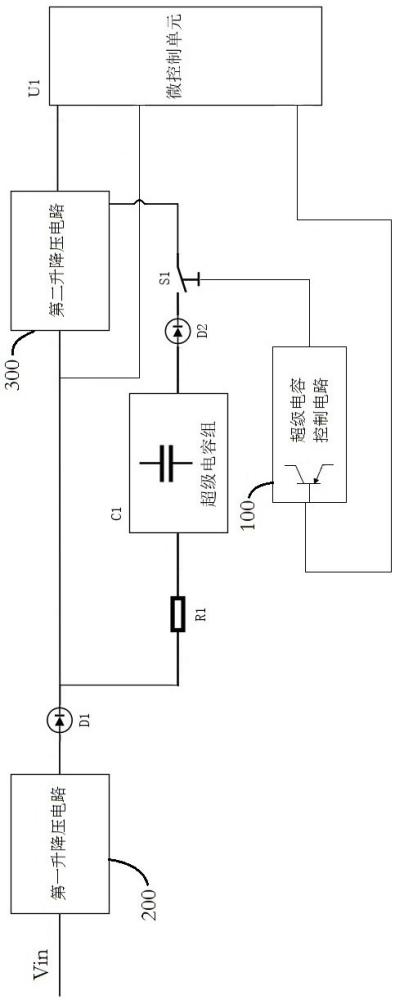
Referring to accompanying drawing 1, the present invention is an uninterruptible power supply system based on supercapacitors, comprising a power supply circuit and a microcontrol unit U1 (i.e., MCU), the power supply circuit is connected with the microcontrol unit U1 and is used for supplying power to the microcontrol unit U1, and further comprises:
supercapacitor group C1, supercapacitor group C1 is connected to the power supply circuit and is provided with a switch S1 between the power supply circuit and the power supply circuit;
the supercapacitor control circuit 100 is used for receiving the signal sent by the microcapacitor control unit U1 to control the switch S1 to control the switch S1 to close or disconnect.
In this embodiment, in practical application, the power supply circuit supplies power to the microcontrol unit U1 so that the microcontrol unit U1 works normally, and also supplies power to the supercapacitor group C1 to charge the supercapacitor group C1, when the power supply circuit is abnormal (such as accidental power failure, When fluctuation occurs, etc.), the supercapacitor group C1 is used as a standby power supply to supply the microcontrol unit U1 normally through discharge, because the supercapacitor group C1 has a certain capacitance value, as an energy storage unit can store a certain amount of electricity, so the microcapacitor unit U1 can maintain a normal working state for a period of time, and when the microcontrol unit U1 detects that the power supply circuit is powered off, it will perform a preset operation (such as saving data) before the energy of the supercapacitor group C1 is exhausted, and when the microcapacitor unit U1 performs the preset operation, then send a signal to the supercapacitor control circuit 100 to control the switch S1 to be disconnected, thereby cutting off the power supply circuit of the supercapacitor group C1, and then controlling the shutdown of the microcontrol unit U1. Effectively avoid the data loss of the microcontrol unit U1 due to the abnormal power supply;Furthermore, because the supercapacitor group C1 has long life and strong anti-interference ability, it has sufficient reliability, so it can provide stable power supply for the microcontrol unit U1 when the power supply circuit is abnormal; furthermore, the supercapacitor group C1 has a large capacity, so that the microcontrol unit U1 has enough time to perform the preset operation, and ensures the stable operation of the uninterruptible power supply system; furthermore, the supercapacitor group C1 allows high-current charging and discharging, so as to achieve the effect of short charging time and high energy conversion efficiency。
In the same way, when the power supply circuit supplies power to the microcontrol unit U1 again, the microcontrol unit U1 sends a signal to the supercapacitor control circuit 100 to control the switch S1 to close, so that the supercapacitor group C1 is connected to the power supply circuit for charging.
In some embodiments, with reference to accompanying drawing 1, the uninterruptible power supply system based on supercapacitor further comprises a first buck-boost circuit 200, the first buck-boost circuit 200 is arranged on the power supply circuit, the input end of the first buck-boost circuit 200 is connected with the power supply, and the output end is electrically connected with the microcontrol unit U1;
The output end of the first buck-boost circuit 200 is also connected with the input end of supercapacitor bank C1 through a power supply branch that is bifurcated from the power supply circuit.
In practical application, different power supply as a pre-power supply system will have different output voltages, such as 5V, 12V, 24V and 48V etc., the present embodiment regulates the output voltage of the power supply by setting up a first buck-boost circuit 200, so that the output voltage conforms to the rated voltage of the normal operation of the microcontrol unit U1 and the supercapacitor group C1, is conducive to avoiding that the microcontrol unit U1 and the supercapacitor group C1 cannot be driven normally by too low voltage, or the microcontrol unit U1 and the supercapacitor group C1 are burned out due to excessive voltage.
Specifically, the first step-boost circuit 200 has two functions of step-up and step-down, and the two functions can be switched to use. For example, the output voltage of the power supply is Vin, the rated voltage of the microcontrol unit U1 is Vout, and the rated voltage of the supercapacitor group C1 is Vc; when Vin>Vout=Vc, the first buck-boost circuit 200 is controlled to switch to a step-down, thereby reducing the output voltage of the power supply; in the same way, when Vin
In some embodiments, referring to accompanying drawing 1, a first diode D1 is arranged between the output end of the first buck-boost circuit 200 and the bifurcation of the power supply circuit; the first diode D1 is used for preventing the current from being backfilled into the first buck-boost circuit 200, and when the power supply circuit is powered off, the first diode D1 can avoid the current flowing into the power supply when the supercapacitor group C1 is discharged, causing the power supply to burn out.
In some embodiments, with reference to accompanying drawing 1, the uninterruptible power supply system based on supercapacitor further comprises a second buck-boost circuit 300, the second buck-boost circuit 300 is arranged on the power supply circuit and is located between the bifurcation of the power supply circuit and the microcontrol unit U1, the input end of the second buck-boost circuit 300 is electrically connected with the output end of the first buck-boost circuit 200 and the output end is connected with the microcontrol unit U1;
The output terminal of the supercapacitor bank C1 is connected with the second buck-boost circuit 300 through a switch S1.
In practical application, different microcontrol unit U1 will have different rated voltages, such as 5V, 12V, 24V and 48V etc., and the present embodiment regulates the input voltage of microcontrol unit U1 by setting up a second buck-boost circuit 300, so that the input voltage conforms to the rated voltage of microcontrol unit U1 normal operation, is conducive to avoiding low voltage can not drive microcontrol unit U1 normally, or excessive voltage causes microcontrol unit U1 to burn out.
Specifically, the second step-boost circuit 300 has two functions of step-up and step-down, and the two functions can be switched and used. When used in combination with the first buck-boost circuit 200, when Vin>Vc > When Vout, the first step-up circuit 200 and the second buck-boost circuit 300 are switched to step-down, thereby reducing the output voltage of the power supply to the rated voltage of the supercapacitor group C1, so that the supercapacitor group C1 works normally, and whether the power supply circuit or the supercapacitor group C1 supplies power to the microcontrol unit U1, the voltage is lowered to the rated voltage of the microcontrol unit U1 again through the second step-up circuit 300, so that the microcontrol unit U1 works normally>; When Vc is >, the first buck-boost circuit 200 is controlled to be switched to a step-down and the second buck-boost circuit 300 is switched to a step-down; when Vout> Vout> Vc, the first buck-boost circuit 200 is switched to a step-down and the second buck-boost circuit 300 is switched to a step-up; when Vout> Vc>Vin, the first buck-boost circuit 200 and the second buck-boost circuit 300 are both switched to a step-up; and when Vc > Vout> Vout Vin, the first buck-boost circuit 200 is controlled to switch to boost and the second buck-boost circuit 300 is switched to step-down, and the uninterruptible power supply system can be used with a variety of microcontrol units U1 by arranging the second buck-boost circuit 300, so that the applicability of the uninterruptible power supply system is further improved.
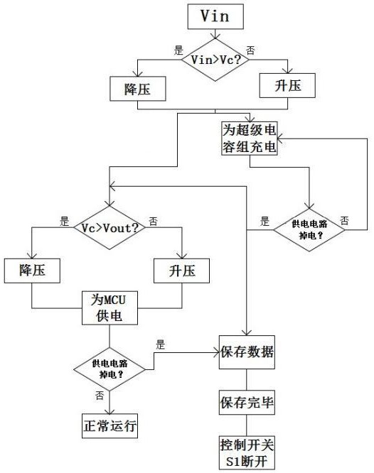
Further, with reference to accompanying drawing 3, the workflow of the uninterruptible power supply system of the present embodiment is described as follows by taking Vin>Vc>Vout as an example (other situations are similar and will not be repeated here):
After Vin is connected to the first buck-boost circuit 200, it is judged that Vin > Vc, then the first buck-boost circuit 200 is controlled to switch to a step-down, and the output Vc of the first buck-boost circuit 200 is charged by the supercapacitor group (the switch S1 is closed under normal conditions); after Vc is connected to the second buck-boost circuit 300, Vc is judged to be > Vout, then control the second buck-boost circuit 300 to switch to step-down, and the second buck-boost circuit 300 outputs Vout to supply power to MCU at this moment; when MCU detects that the power supply circuit is power-off, the supercapacitor group begins to discharge for MCU, and the supercapacitor group outputs Vc and step-down to Vout through the second buck-boost circuit 300, so that the MCU maintains normal power supply and carries out data saving, after the data is saved, the MCU sends a signal to the supercapacitor control circuit 100 to control the switch S1 to be disconnected, the supercapacitor group stops discharging, and the MCU shuts down。
In some embodiments, referring to accompanying drawing 1, a second diode D2 is arranged between the output terminal of supercapacitor group C1 and the switch S1; the second diode D2 is used for preventing current from being backfilled into supercapacitor group C1, and when the power supply circuit is power-off, the second diode D2 can limit the current flow direction when supercapacitor group C1 is discharged, and ensure that supercapacitor group C1 can normally supply power to microcontrol unit U1.
In some embodiments, referring to accompanying drawing 1, a first resistor R1 is arranged between the input terminal of supercapacitor group C1 and the power supply circuit; the first resistor R1 is used for limiting the current flowing into supercapacitor group C1 so that supercapacitor group C1 can be charged in a constant current state, and the first resistor R1 is arranged so that supercapacitor group C1 can be charged in constant current mode, so as to ensure that the charging process of supercapacitor group C1 is stable and safe.
In some embodiments, the supercapacitor group C1 comprises 1 supercapacitor.
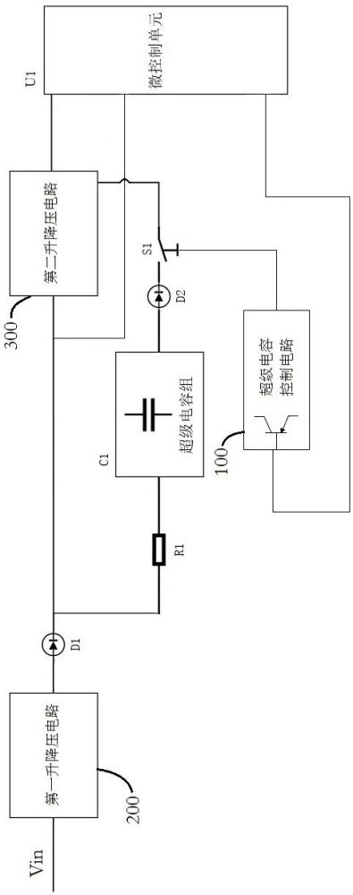
In some embodiments, with reference to accompanying drawing 2, supercapacitor group C1 comprises a plurality of supercapacitors, the supercapacitors are divided into a plurality of blocks, each block comprises at least one supercapacitor, and two adjacent blocks are connected in parallel with each other.
In practical application, the time required for the microcontrol unit U1 to perform the preset operation is different in different application scenarios, and the withstand voltage requirements for supercapacitor group C1 are also different simultaneously, so the embodiment forms supercapacitor group C1 with different capacitance values and different withstand voltage values through the combination of a plurality of supercapacitors, so as to meet the actual demand.
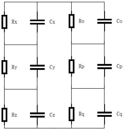
Further, with reference to Figure 2, each block comprises a plurality of supercapacitors, and a plurality of supercapacitors in the same block are connected in series with each other.
For example, the larger the number of supercapacitors, the larger the capacitance of supercapacitor group C1, which can store more energy and thus extend the discharge time to meet the time required for different microcontrol unit U1 to perform preset operations.
For example, the larger the number of supercapacitors connected in series, the greater the working voltage of supercapacitor bank C1, which increases the withstand voltage value of supercapacitor bank C1 to meet different withstand voltage requirements.
Further, with reference to Figure 2, each supercapacitor is connected with a corresponding second resistor, and the second resistor can be arranged so that each supercapacitor can be charged as evenly as possible.
Specifically, the supercapacitor group C1 comprises six supercapacitors, namely the first supercapacitor Cx, the second supercapacitor Cy, the third supercapacitor Cz, the fourth supercapacitor Co, the fifth supercapacitor Cp and the sixth supercapacitor Cq;
Wherein the first supercapacitor Cx, the second supercapacitor Cy and the third supercapacitor Cz are connected in series to form the first block, and the first supercapacitor Cx is connected with a third resistor Rx, the second supercapacitor Cy is connected with a fourth resistor Ry, the third supercapacitor Cz is connected with a fifth resistor Rz; the fourth supercapacitor Co, The fifth supercapacitor Cp and the sixth supercapacitor Cq are connected in series to form the second block, and the fourth supercapacitor Co is connected with a sixth resistor Ro, the fifth supercapacitor Cp is connected with a seventh resistor Rp, and the sixth supercapacitor Cq is connected with an eighth resistor Rq, and the first block and the second block are connected in parallel.
It should be noted that the above third resistor Rx, the fourth resistor Ry, the fifth resistor Rz, the sixth resistor Ro, the seventh resistor Rp and the eighth resistor Rq all belong to the above second resistor.
In the description of this specification, references to the terms "one embodiment", "some embodiment", "schematic embodiment", "example", "specific example", or "some examples", etc., are intended to be included in at least one embodiment or example of the present invention in conjunction with the specific features, structure, materials or features described in the embodiments or examples. In this specification, indicative representations of the above terms do not necessarily refer to the same embodiments or examples. Further, the specific features, structures, materials, or features described may be combined in an appropriate manner in any one or more embodiments or examples.
The above are only some embodiments of the present invention. For a person skilled in the art, under the premise of not departing from the idea of the present invention, a number of deformations and improvements can also be made, which all belong to the scope of protection of the present invention.










 400-4929-0909
 contact@catarc.com.cn