Technical Field
The utility model belongs to the technical field of automatic transmissions, and particularly relates to an automatic transmission with P manual unlocking devices.
Background Art
Automated. Intelligent is the development trend of future automobile, derailleur as the power transmission device of car, and its degree of automation nature is the hot spot of car trade research. The automatic transmission with the electronic gear shifting is characterized in that the height of the vehicle type configuration is improved to a certain extent, and the degree of automation of the motorcycle type is also reflected.
The electronic shift is the driver manipulating the electronic shift lever, and the transmission automatically completes the gear shift command according to the driver request. During the shifting process, the driver feels a shift resistance that is not transmitted to the transmission internal mechanical structure. At present, the electronic shift structure of the automatic transmission has two forms, namely external and built-in. The external type is the most common electronic gear shifting structure, needs to rely on the actuator to drive the transmission gear shifting shaft to rotate, and the gear shifting is completed.
But when the automobile breaks down, such as battery shortage, complete vehicle communication obstacle, electronic shift controller or actuator failure, etc, the electronic shift actuator cannot work, the automobile cannot exit P, and the trailer and the cart are difficult.
A P-gear manual unlocking mechanism of an existing external electronic gear-shifting structure needs no external tools such as a wrench or P-gear manual unlocking device, so that the actual use requirement of a user cannot be met.
Content of the utility model
(I) technical problem to be solved
The utility model provides an automatic transmission with P manual unlocking device that keeps off, this automatic derailleur that has P keep off manual unlocking device aims at solving current external electronic gear shifting structure because no P keeps off manual unlocking device, leads to the vehicle can't withdraw P the technical problem who keeps off under the condition of battery shortage, communication trouble, electronic shift executor failure.
(Two) technical scheme
One end of the transmission gear shifting shaft is a rod shape; the control P end penetrates through the control hole; the control end penetrates through the control hole; the inner wall of the control hole comprises at least one force applying surface; and the force applying surface is matched with the stress surface. Rotating the operating lever, the force applying surface transmits torque to the force bearing surface, so as to drive the transmission gear shifting shaft to rotate.
, The control end comprises two opposite force bearing surfaces, and the control hole comprises two force applying surfaces which are respectively attached to the two stress surfaces.
, The operating rod comprises a disc-shaped sleeve part and a handle part connected with the sleeve part, wherein the control hole is arranged on the sleeve part, and the whole handle part is rod-shaped.
, One end of the handle portion remote from the sleeve portion is rounded, and the sleeve portion and the handle portion are smoothly connected.
, The operating lever is integrally formed of a metal material.
, The length of the joystick is 50 - 80mm.
, The handle part is in the shape of a straight rod or a step rod.
, The automatic transmission with P manual unlocking devices further comprises an actuator mounting bracket and an electronic shift actuator mounted on the actuator mounting bracket, wherein a top end of the transmission gear shifting shaft is connected with an output shaft of the electronic shift actuator.
, The transmission shifting shaft and the operating lever are welded and connected.
, Through the interference fit of the control hole and the control end, the transmission gear shifting shaft and the operating rod are fixedly connected.
(Three) benefits
Compared with the prior art, the automatic transmission with P-gear manual unlocking device has the beneficial effects that the automatic transmission has the advantages of being simple in structure and convenient to use.
(1) The utility model relates to an automatic derailleur with P keeps off manual unlocking device, and newly added operating lever is a part based on derailleur gear shift axle, will not influence the overall performance of automatic transmission, need not improve the structure and the position of other parts.
(2) Utilizes the utility model relates to an automatic derailleur with P keeps off manual unlocking device, need not to help the help of external instrument, can realize external electronic shift P keeps off the function of manual unblock, and the structure is stable. The operation is convenient, and the practicality is strong, can satisfy user's actual use demand.
Description of drawings
The features and advantages of the present invention will become more clearly understood by reference to the accompanying drawings, which are schematic and are not to be construed as limiting the invention in the accompanying drawings.
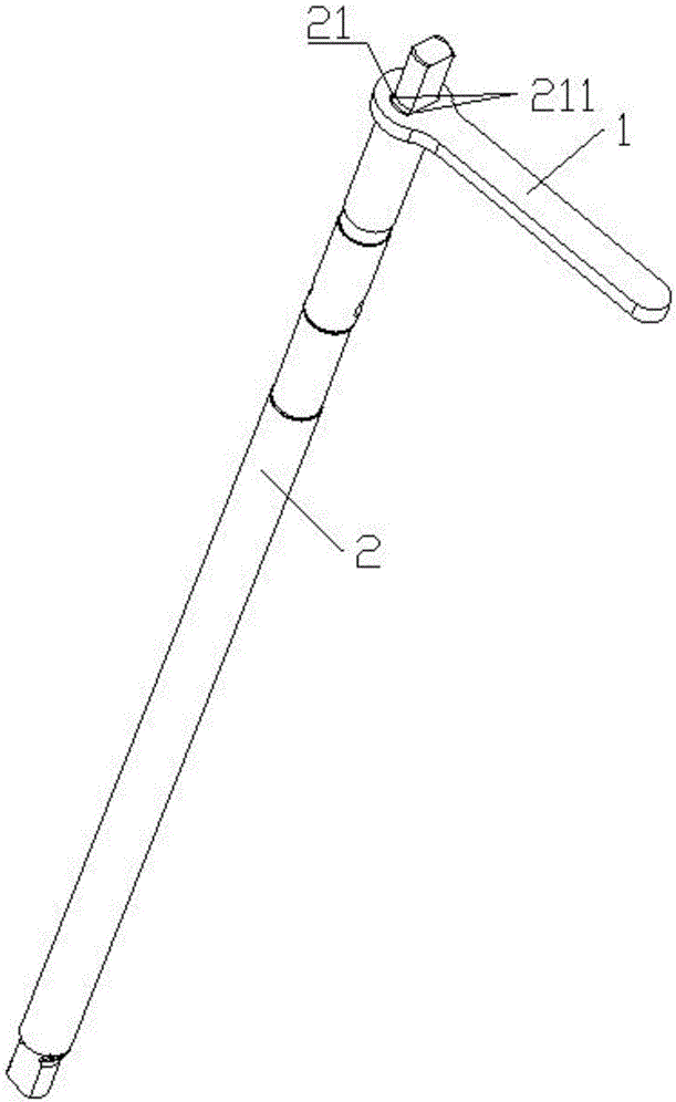
1 Is a schematic diagram of a connection state between an operating lever and a transmission shaft of a transmission with P manual unlocking device according to an embodiment of the present invention.
2 Is a schematic view of P of a joystick in an automatic transmission with 1st-gear manual unlocking device according to an embodiment of the present invention.
3 Is a schematic view of P of a joystick in an automatic transmission with 2nd-gear manual unlocking device according to an embodiment of the present invention.
4 Is a schematic view of P of a joystick in an automatic transmission with 3rd-gear manual unlocking device according to an embodiment of the present invention.
5 Is a schematic structural view of an automatic transmission with P-gear manual unlocking device according to an embodiment of the present invention.
6 Is a partial enlarged view at 5 of FIG. A.
Drawings are given in the drawing.
1.Joystick, 2. Shift shaft of transmission, 3. Electronic shift actuator, 4. Actuator mounting bracket, 11. Muff-coupling part, 12. Handle hand, 21. Control terminal, 111. Control hole, 1111. Force applying surface 211. Stress surface.
Mode of execution
In order to make the above objects, features and advantages of the present disclosure more comprehensible, specific embodiments of the present invention will be described in detail with reference to the accompanying drawings. In the following description, numerous specific details are set forth in order to provide a thorough understanding of the present invention. The present invention may, however, be embodied in many different forms than those described herein, and it will be apparent to those skilled in the art that similar modifications may be made without departing from the scope of the present invention.
In the description of the present disclosure, unless expressly stated and defined otherwise, the terms' connected, '' connected, 'and' connected ' are to be construed broadly, and may be, for example, fixedly connected, removable, or integrally connected. The utility model can be a mechanical connection or an electric connection, can be directly connected or indirectly connected through an intermediate medium, can be communicated with the inside of the two elements, and can also be a 'transmission connection', that is, through belt transmission. The power connection is carried out in various suitable manners, such as gear transmission or chain wheel transmission. It will be understood by those skilled in the art that the specific meanings of the above terms in the present invention may be specifically understood.
To FIG. 1-6, an automatic transmission with P-gear manual unlocking device includes a transmission shift shaft 2 and a lever 1, and the control end 2 includes at least one stress surface 21, a control hole 21 penetrating therethrough, a control end 211 penetrating through the control hole 211, and a force applying surface 1 attached to the force receiving surface 1 111 through the control hole. The control hole 1111 111 is provided with an 111 211 actuating surface 21 1111. The rotating lever 1 and the force application surface 1111 transmit torque to the force receiving surface 211, so as to rotate the transmission shifter shaft 2. The automatic transmission having P manual unlocking means further includes an actuator mounting bracket 4 and an electronic shift actuator 4 mounted on the actuator mounting bracket 3, and a top end of the transmission shift shaft 2 is connected to an output shaft of the electronic shift actuator 3.
In the present embodiment, the joystick 1 is a new structure, and specifically, the lever 2 is added to the upper portion of the transmission shift shaft 1, and the lever 1 is directly attached to the upper portion of the transmission shift shaft 1 (that is, the control end 2) via the force receiving surface 21 of the planar structure and the force surface 211 1111 of the planar structure. The operation lever 1 does not affect the overall performance of the automatic transmission, and the structure and the position of other parts are not improved.
Note that the control end 21 is not the uppermost end of the transmission shift shaft 2 but is close to the top, and the top end of the transmission shift shaft 2 is connected to the output shaft of the electronic shift actuator 3. The transmission shifter shaft 2 has a bottom end connected to a shift fork.
Normally, gear shifting is completed by driving the transmission shift shaft 3 to rotate by the electronic shift actuator 2.
When a vehicle fails, a battery failure occurs, for example. When the whole vehicle communication barrier, the electronic shift controller, or the electronic shift actuator 3 fail, the electronic shift actuator 3 cannot drive the transmission shift shaft 2 to rotate to complete the gear switching, and the operation lever 1 and the force application surface 1 transmit torque to the force receiving surface 1111 1 to rotate the transmission shift shaft 2 211 when the lever 2 is rotated. The whole process can realize the manual unlocking function of the external electronic gear shifting P without the help of external tools, and is convenient to operate and good in reliability.
, The automatic transmission with P-gear manual unlocking device not only realizes the manual unlocking function of the external electronic gear shifting P without influencing the product performance and does not need external tools, but also is convenient to operate and good in reliability.
To the specific embodiment of the utility model, the control end 21 comprises two opposite force bearing surfaces 211, and the control hole 111 comprises two force applying surfaces 211 respectively attached to the two stress surfaces 1111. To the embodiment, by arranging the two stress surfaces 211, the torque can be effectively transmitted.
To the embodiment of the utility model, the operating lever 1 comprises a disc-shaped sleeve part 11 and a handle part 11 connected with the sleeve part 12, the control hole 111 is arranged on the sleeve part 11, and the whole hand 12 is rod-shaped. The disk-shaped sleeve portion 11 facilitates engagement with the transmission shift shaft 2, and the rod-shaped grip portion 12 facilitates hand-held operation.
To the embodiment of the utility model, one end of the hand 12 far away from the sleeve part 11 is rounded, and the sleeve part 11 and the handle part 12 are smoothly connected. This structure does benefit to avoiding stress concentration, improves the comfort level when using simultaneously.
To the embodiment of the utility model, the operating lever 1 is integrally formed of a metal material. This solution is advantageous to improve the overall performance of the operating lever 1.
To the embodiment of the utility model, the length of the handle 1 is 50 - 80 mm . the whole hand 12 is directly rod-shaped (shown 2), or the whole hand 12 is stepped rod-shaped (shown 3 and 4), and in practical application, the length and the shape of the operating rod 1 can be flexibly designed according to the actual operating space of the automatic gearbox. Note that the structure in which the handle portion 12 is integrally formed in a stepped rod shape includes two structures shown 3 and 4, and may of course be other stepped bar-shaped structures.
To a specific embodiment of the present invention, the transmission shift shaft 2 and the operating lever 1 are welded together. By performing spot welding at the contact surface of the lever 1 and the transmission shift shaft 2, a problem of noise caused by shaking of the joystick 1 can be avoided. Of course, a fixed connection between the transmission shift shaft 2 and the lever 1 may be implemented in other ways, for example, by an interference fit of the control hole 111 with the control end 21 to achieve a fixed connection between the transmission shift shaft 2 and the lever 1.
Compared with the prior art, the utility model discloses based on current automatic gearbox to improve, simple structure, the practicality is strong. To the automatic transmission with P-gear manual unlocking device, the function of manual unlocking of the external electronic gear shifting P is realized without influencing the product performance and without the help of external tools, and the requirements of reliability and operability are met.
While the embodiments of the present invention have been described with reference to the accompanying drawings, those skilled in the art may make various modifications and variations without departing from the spirit and scope of the present invention, all falling within the scope defined by the appended claims.
Automatic transmission with P-gear manual unlocking device










 400-4929-0909
 contact@catarc.com.cn