Contents of the Invention
To solve the problem of the prior art due to the absence of lane line ground marking within the intersection, it is not possible to automatically generate a high-precision map of the intersection based on an image and a point cloud data source, the present invention provides a high-precision map generation method for intersections, an apparatus, an electronic device and a storage medium, the scheme is as follows:
On the one hand, it provides a high-precision map generation method for intersections, including:
Based on the parameters of the intersection to be processed and the topological relationship of the road reference line outside the intersection, the starting node of the reference line in the intersection to be processed is determined;
Based on the starting node of the reference line in the intersection, determine the reference line within the intersection of the intersection to be processed on different road turns; The reference line within the intersection indicates the direction of travel of the lane;
According to the intersection reference line, the lane line starting node of the corresponding lane in the intersection is determined, and the lane line in the intersection is generated based on the starting node of the lane line;
Determine the lane centerline starting node based on the lane line in the intersection, and generate the lane centerline in the intersection corresponding to the lane line in the intersection based on the lane centerline starting node;
Based on the intersection within the reference line, the intersection lane line and the intersection within the lane centerline, and the intersection within the reference line, the intersection within the lane centerline and the traffic facility object related to the intersection to be processed to establish a logical association model, the intersection high-precision map of the intersection to be processed is generated.
Optionally, it also includes:
According to the pre-collected picture data of the intersection to be processed, the intersection type is determined, and the intersection type is taken as the first parameter;
Based on the road model data of the intersection of the road to be processed, the number of inbound and outbound roads is generated, and the number of roads driven in and out is taken as the second parameter;
According to the correlation relationship between the road entering the intersection and the direction arrow of the road sign, the turning relationship of the road at the intersection is determined, and the turning relationship of the road at the intersection is taken as the third parameter; The road turning relationship at the intersection includes a straight, left and right turn; The signpost direction arrow indicates that the vehicle performs a turn in different directions on the road at the intersection;
Based on the first parameter, the second parameter and the third parameter, the parameters of the intersection to be processed are generated.
Optionally, based on the parameters of the intersection to be processed and the topological relationship of the road reference line outside the intersection, determine the starting node of the reference line within the intersection to be processed comprising:
Obtain the off-junction road reference line and stop line of the intersection road with the intersection of the to be processed, and generate the four-to-range road segment of the road to be processed based on the stop line; The four to the range of road sections includes a section of road intersecting with the intersection to be treated;
Based on the parameters of the intersection to be processed and the topological relationship of the road reference line outside the intersection within the four to the range of road sections, the road reference line outside the intersection is divided into driving intersection road reference line and driving out of the intersection road reference line that meet the preset conditions;
Determining the set of nodes connected to the road reference line and the exit road reference line and the intersection to be processed, the node set comprises a set of driving in nodes and a set of driving out nodes;
According to the road steering relationship of the driving intersection, determine the corresponding driving nodes of each driving node in the set of nodes in different road steering relationships;
Based on the respective driving node and the respective driving out node to determine the starting node of the reference line within the intersection.
Optionally, the intersection outside the road reference line is divided into driving intersection road reference lines and driving out of the intersection road reference lines that meet the preset conditions comprising:
Based on the topological relationship model of the road reference line outside the intersection, the type of the intersection and the number of roads entering and leaving, the collection of road reference lines and the collection of road reference lines of the road at the intersection are determined;
Calculate the average distance of each road reference line outside the intersection to the center of the intersection to be processed;
The said road reference line with the smallest average distance is determined as the driving intersection road reference line and the driving intersection road reference line that meets the preset conditions.
Optionally, according to the driving intersection road steering relationship, to determine the set of nodes in each driving node in a different road steering relationship corresponding to each driving node comprising:
According to the road steering relationship of the driving intersection, the road lane line intersecting with the respective driving node is determined;
Calculate the distance value and direction value of the road lane line where each driving node intersects the driving node to be matched; The to be matched drive-in node is any of the incoming nodes in the set of driven-in nodes;
The corresponding driving out node of the maximum distance value and the positive direction value is the driving out node of the node to be matched in the left turning direction; The corresponding driving out node of the maximum distance value and the negative value of the direction is the driving out node of the node to be matched in the right turning direction;
Calculate the angle between the direction line formed by the each driving node and the driving node to be matched and the road lane line;
The corresponding driving out node with the smallest angle value is the driving out node in the straight direction of the driving node to be matched.
Optionally, based on the starting node of the reference line within the intersection, determine the intersection to be processed on different road turns within the reference line comprising:
Obtain the first road lane line that intersects within the preset range of the incoming node and the second road lane line that intersects within the preset range of the exit node;
For the first road lane line, determine the first direction vector of the nearest two node connection segments of the driving node and the first road lane line connection;
For the second road lane line, determine the second direction vector of the nearest two node connection segments of the driving node and the second road lane line connection;
Based on the driving node, the driving out node, the first direction vector and the second direction vector, the intersection reference line to be processed on different road turns is determined.
Optionally, the lane centerline starting node is determined based on the lane line within the intersection, and the lane centerline within the intersection corresponding to the lane lane line corresponding to the lane centerline within the intersection is generated based on the lane centerline starting node of the lane within the intersection comprises:
For the lane line in the intersection, obtain the corresponding left lane line and right lane line, and determine the length of the left lane line and the length of the right lane line;
For each point on the left lane line, based on the distance between the point and the first endpoint of the left lane line, the length of the left lane line and the length of the right lane line, the corresponding point of each point on the right lane line corresponding to the point is determined;
Determine the midpoint of each point on the left lane line and the corresponding point of the connection line, and obtain a plurality of the lane centerline starting nodes;
Based on the starting node of the lane centerline, the lane centerline in the intersection corresponding to the left lane line and the right lane line is generated.
Optionally, based on the intersection within the reference line, the intersection lane line and the intersection within the lane centerline, and the intersection within the reference line, the intersection within the lane centerline and the traffic facility object associated with the intersection to be processed to establish a logical association model, to generate the intersection of the intersection to be treated high-precision map comprising:
Based on the intersection reference line, the intersection lane line and the intersection lane centerline within the intersection are generated to generate the intersection geometry model and topological relationship of the intersection to be processed;
Construct the reference line in the intersection, the lane centerline in the intersection and the logical association relationship between the traffic facility object in the intersection to be processed;
Based on the intersection road geometry model and topological relationship and the logical association relationship to generate the intersection high-precision map of the intersection to be processed.
On the other hand, an intersection high-precision map generation device is provided, which is characterized by, comprising:
The generator module of the reference line start node in the intersection is used to determine the starting node of the reference line in the intersection to be processed based on the parameters of the intersection to be processed and the topological relationship of the road reference line outside the intersection;
In-intersection reference line generation module for determining the intersection reference line on different road turns based on the starting node of the reference line in the intersection; The reference line within the intersection indicates the direction of travel of the lane;
The lane line generation module in the intersection is used to determine the lane line start node of the corresponding lane according to the reference line in the intersection, and generate the lane line in the intersection based on the starting node of the lane line;
The lane centerline generation module in the intersection is used to determine the lane centerline starting node based on the lane line in the intersection, and to generate the lane centerline in the intersection corresponding to the lane line in the intersection based on the lane centerline starting node;
HD map generation module for generating the intersection HD map based on the intersection within the intersection, the lane line within the intersection and the lane centerline within the intersection, and the reference line in the intersection, the lane centerline within the intersection and the traffic facility object related to the intersection to be processed, to generate the intersection HD map of the intersection to be processed.
Optionally, the intersection HIGH-precision map generation apparatus further comprises:
The first parameter determination module for determining the intersection type according to the pre-collected picture data of the intersection to be processed, and the intersection type as the first parameter;
The second parameter determination module for generating the number of roads in and out of the road based on the road model data of the intersection of the intersection with the intersection of the intersection to be processed, the number of roads driven in and out as the second parameter;
The third parameter determination module, used to determine the turning relationship of the road at the intersection according to the correlation relationship between the road entering the intersection and the direction arrow of the road sign, and the turning relationship of the road at the driving intersection is taken as the third parameter; The road turning relationship at the intersection includes a straight, left and right turn; The signpost direction arrow indicates that the vehicle performs a turn in different directions on the road at the intersection;
Parameter configuration module for generating the parameters of the to be processed junction based on the first parameter, the second parameter and the third parameter.
Optionally, the reference line start node generation module within the intersection further comprises:
Four to range determination module for obtaining the intersection of the intersection road intersecting the road to be processed and the stop line, and based on the stop line to generate the four to range of the road section of the road to be treated; The four to the range of road sections includes a section of road intersecting with the intersection to be treated;
Road reference line division module for dividing the road reference line outside the intersection into driving intersection road reference lines and exit road reference lines that meet the preset conditions based on the parameters of the intersection to be treated and the intersection outside the road reference line topology relationship within the four to the range of road segments;
Road reference line node determination module for determining the set of nodes connected to the road reference line and the road reference line of the road exit road and the intersection to be processed, the node set comprises a collection of driving in nodes and a collection of driving out nodes;
Road reference line node division module, for the purpose of the road steering relationship according to the driving intersection road steering relationship, to determine the node in the set of the driving node in different road steering relationship corresponding to each driving node;
The reference line within the intersection start node determination module for determining the starting node of the reference line in the intersection based on the respective entry node and the exit node.
Optionally, the road guide division module comprises:
The first inbound and outbound road reference line determination unit, for determining the collection of inlet road reference lines and the collection of driving intersection road reference lines based on the topological relationship model of the road reference line outside the intersection, the type of the intersection and the number of roads entering and exiting the road;
The first calculation unit for calculating the average distance of each road reference line outside the intersection to the center of the intersection to be treated;
The second inbound and outbound road reference line determination unit for determining the road reference line with the smallest average distance is determined to be the driving intersection road reference line and the driving intersection road reference line that meets the preset conditions.
Optionally, the road guide node division module comprises:
Road lane line determination unit, for determining the road lane line intersecting with each entry node according to the road steering relationship of the driving intersection;
The second calculation unit, for calculating the distance value and direction value of the road lane line where each driving node intersects the driving node to be matched; The to be matched drive-in node is any of the incoming nodes in the set of driven-in nodes;
The first driving out node is divided into units for the corresponding driving out node of the maximum distance value and the positive direction value as the driving node to be matched in the left turning direction of the driving node; The corresponding driving out node of the maximum distance value and the negative value of the direction is the driving out node of the node to be matched in the right turning direction;
The third calculation unit, for calculating the angle value between the direction line formed by each driving node and the driving node to be matched with the road lane line;
The second drive-out node is divided into units for the corresponding driving-out node with the smallest angle value as the driving-out node to be matched in the straight direction of the driving-out node.
Optionally, the reference line generation module within the intersection comprises:
Road lane line acquisition unit, which is used to obtain the first road lane line that intersects within the preset range of the incoming node and the second road lane line that intersects within the preset range of the exit node;
Obtain the first road lane line that intersects within the preset range of the incoming node and the second road lane line that intersects within the preset range of the exit node;
For the first road lane line, determine the first direction vector of the nearest two node connection segments of the driving node and the first road lane line connection;
For the second road lane line, determine the second direction vector of the nearest two node connection segments of the driving node and the second road lane line connection;
Based on the driving node, the driving out node, the first direction vector and the second direction vector, the intersection reference line to be processed on different road turns is determined.
Optionally, the lane centerline generation module within the intersection comprises:
Lane line length determination unit, used to obtain the corresponding left lane line and right lane line for the lane line in the intersection, determine the length of the left lane line and the length of the right lane line;
Equidistance proportional method calculation unit for each point on the left lane line, based on the distance of the point to the first endpoint of the left lane line, the length of the left lane line and the length of the right lane line to determine the corresponding point of each point on the right lane line corresponding to the point;
Lane centerline start node generates a unit for determining the midpoint of each point on the left lane line and the corresponding point of the connection line, and obtaining a plurality of said lane centerline starting nodes;
The lane centerline determination unit within the intersection is used to generate the lane centerline within the intersection corresponding to the left lane line and the right lane line based on the starting node of the lane centerline.
Optionally, the HD map generation module includes:
Intersection road geometry model and topological relationship generation unit, for generating the intersection road geometry model and topological relationship of the intersection to be processed based on the reference line within the intersection, the lane line within the intersection and the lane centerline within the intersection;
Logical association relationship generation unit for constructing the reference line within the intersection, the lane centerline within the intersection and the traffic facility object in the intersection to be processed;
HD map generation unit for generating the intersection HD map of the intersection to be processed based on the intersection road geometry model and topological relationship and the logical association relationship.
On the other hand, there is provided an electronic device, comprising a processor and a memory, the memory stores at least one instruction or at least one program, the at least one instruction or the at least one program is loaded by the processor and performed steps to implement the above method.
On the other hand, a computer-readable storage medium is provided, wherein the computer-readable storage medium stores at least one instruction or at least one program, the at least one instruction or the at least one program is loaded by the processor and performed steps to implement the above method.
On the other hand, there is provided a computer program product or computer program, the computer program product or computer program comprising a computer instruction, the computer instructions stored in a computer-readable storage medium, the processor of the computer device reads the computer instructions from the computer-readable storage medium, the processor executes the computer instructions, so that the computer device performs the steps of the above method.
Using the above technical solution, the present invention has the following beneficial effects:
The present invention by treating the intersection parameterization setting, based on the intersection intersection to be processed road outside the road reference line topology relationship to determine the reference line, lane line and lane center line in the intersection, and then based on logical association technology, to achieve the regular intersection of high-precision map data automatic generation, greatly improve the efficiency of manual mapping, so that in the absence of lane line ground identification in the intersection, can also be based on the intersection corresponding to the road section side of the high-precision map road data model to generate a high-precision map of the intersection.
Other features and advantages of the present invention will be described in detail in the subsequent specific embodiments section.
Specific embodiments
The following will be combined with the accompanying drawings in an embodiment of the present invention, the technical solution in an embodiment of the present invention is clearly and completely described. Obviously, the embodiments described are only a portion of the embodiments of the present invention, and not all embodiments. Based on embodiments in the present invention, all other embodiments obtained by those of ordinary skill in the art without doing creative work, are within the scope of protection of the present invention.
As used herein, "an embodiment" or "embodiment" refers to a particular feature, structure, or characteristic that may be included in at least one embodiment of the present invention. In the description of the present invention, it is to be understood that the term "up", "down", "top", "bottom" and the like indicates the orientation or position relationship based on the drawings, only to facilitate the description of the present invention and simplify the description, and not to indicate or imply that the means or elements referred to must have a specific orientation, structured and operated in a particular orientation, and therefore cannot be understood as a limitation of the present invention. Further, the terms "first", "second" are for descriptive purposes only and cannot be construed as indicating or implying relative importance or implicitly indicating the number of technical features indicated. Thus, the characteristics limited to "first" and "second" may include one or more such features expressly or implicitly. Moreover, the terms "first", "second", etc. are used to distinguish similar objects, rather than to describe a particular order or sequencing. It should be understood that the data used in this manner are interchangeable in appropriate cases, so that the embodiments of the present invention described herein can be implemented in order other than those illustrated or described herein.
It should be noted that, referring to FIG. 1, the high-precision map road data model based on the present invention is a data model formulated in combination with the navigation electronic map and the high-precision map production specification to meet the needs of automatic driving, including road reference lines, lane boundary lines, lane centerlines, ground and aboveground road ancillary facilities, parking areas and speed limit signs.
The topological relationship referred to hereinafter referred to in the present invention refers primarily to the connecting relationship between the reference line, the lane line and the lane center line; The correlation relationship mainly refers to the relationship between the traffic auxiliary facilities and the road or lane, such as the logical relationship between the stop line and the lane, the logical relationship between the road boundary and the reference line, etc.; The intersection to be treated is a regular intersection, which refers to an intersection that can be parameterized.
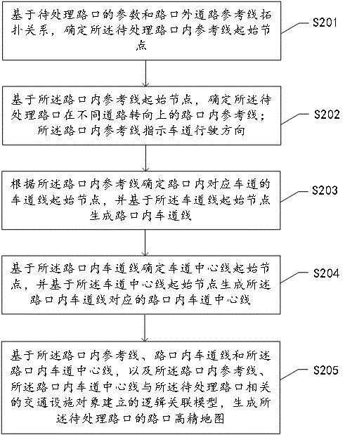
Referring to FIG. 2, which shows a schematic diagram of a high-precision map generation method at an intersection provided by an embodiment of the present invention. The present specification provides a method of operation as described in an embodiment or flowchart, but based on conventional or unconventional labor may include more or fewer operating steps. The sequence of steps enumerated in an embodiment is only one of the many steps in the order of execution, does not represent a unique order of execution. In practice, when the system apparatus or product is executed, it may be executed sequentially or in parallel according to an embodiment or the method shown in the accompanying drawings (e.g., a parallel processor or a multithreaded environment). Embodiments of the present invention provides a method for generating a high-precision map of the intersection comprising:
S201, based on the parameters of the intersection to be processed and the topological relationship of the road reference line outside the intersection, determine the starting node of the reference line in the intersection to be processed;
Specifically, first based on the road section prior information and manual visual interpretation of the parameterized configuration rules of the pending intersection, the parameters of the to be treated intersection comprising the type of intersection, the number of roads entering and exiting the road and the turning relationship of the road at the intersection, in one possible embodiment, according to the pre-collected picture data of the intersection to be processed, determine the intersection type, the type of the intersection as the first parameter P1; Based on the road model data of the intersection road with the intersection of the intersection to be processed, the number of inbound and outbound roads is generated, and the number of roads driven in and out is taken as the second parameter P2; According to the correlation relationship between the road at the intersection and the direction arrow of the road sign, the steering relationship of the road at the intersection is determined, and the turning relationship of the road at the intersection is taken as the third parameter P3; The road turning relationship at the intersection includes a straight, left and right turn; The signpost direction arrow indicates that the vehicle performs a turn in different directions on the road at the intersection; Based on the first parameter, the second parameter and the third parameter, the parameters of the to be treated intersection are generated, with {P1, P2, P3} as the parameter marking the to be treated intersection, for the subsequent automatic generation of the intersection HIGH-precision map
Referring to FIG. 3, in one possible embodiment, step S201 further comprises:
S301, obtain the intersection of the road outside the intersection and stop line with the intersection of the intersection to be processed, and generate a four-to-range road section of the road to be treated based on the stop line; The four to the range of road sections includes a section of road intersecting with the intersection to be treated;
S302, based on the parameters of the intersection to be treated and the intersection outside the road reference line topology relationship within the four to the range of road sections, the road reference line outside the intersection is divided into driving intersection road reference line and driving out of the intersection road reference line that meets the preset conditions;
Specifically, according to the geometric intersection relationship of the road space, query all the road reference lines and stop lines outside the intersection of the intersection to be processed, and automatically generate the four to the range of the road section of the intersection to be processed based on the stop line, and the road data model such as the road data model of the road reference line outside the intersection mentioned subsequently refers to the road data model of the four to the range of the road section of the road to be processed; Based on the intersection type, the number of inbound and outbound roads and the intersection road reference line topology relationship outside the intersection road reference line grouping, in one possible embodiment, step S302 further comprises:
(1) Based on the topological relationship model of the road reference line outside the intersection, the type of the intersection and the number of roads entering and leaving, the collection of road reference lines and the collection of road reference lines of the road exit of the intersection are determined;
(2) Calculate the average distance between each road reference line outside the intersection and the center of the intersection to be treated;
(3) The said road reference line with the smallest average distance is determined as the driving intersection road reference line and the driving intersection road reference line that meets the preset conditions.
Specifically, with reference to Figure 5, the road reference line of the driving intersection is the arrow pointing to the arrow line of the intersection to be processed, and the set of road reference lines of the driving intersection is {L1, L2, L3, L4}; The exit road reference line is an arrow away from the arrow line of the intersection to be processed, and the set of road reference lines for the exit road is {K1, K2, K3, K4}. where Li or Ki contain one or more guides, i= 1, 2, 3, 4. If Li or Ki contains more than one reference line, calculate the average distance![]() from the center of the intersection to be processed according to Formula (1), retain the reference line corresponding to the minimum average distance
from the center of the intersection to be processed according to Formula (1), retain the reference line corresponding to the minimum average distance![]() , and realize the set Li or Ki Contains only one driving intersection road guide that meets the preset conditions (i.e., the arrow points to the solid arrow line of the intersection to be processed), the exit road guide (i.e., the arrow away from the arrow solid line of the to be processed intersection) and a plurality of dotted reference lines corresponding to the connection, wherein the preset condition is the road reference line with the lowest average distance from the center of the to be processed intersection.
, and realize the set Li or Ki Contains only one driving intersection road guide that meets the preset conditions (i.e., the arrow points to the solid arrow line of the intersection to be processed), the exit road guide (i.e., the arrow away from the arrow solid line of the to be processed intersection) and a plurality of dotted reference lines corresponding to the connection, wherein the preset condition is the road reference line with the lowest average distance from the center of the to be processed intersection.
![]() (1)
(1)
where [X, Y] represents the planar coordinates of the center of the intersection to be processed; [Xi,Yi] is the planar coordinate of the nodes on the road reference line contained in Li or Ki, and n is the number of nodes on the corresponding road reference line,![]() which is the average distance.
which is the average distance.
S303, determining the set of nodes connected to the road reference line and the road reference line of the exit road and the intersection to be processed, the node set comprises a set of driving in nodes and a set of driving out nodes;
Specifically, according to the inbound road reference line and the exit road reference line obtained in step S302, find the node connecting the reference line with the intersection to be processed, including the dotted reference line node, as shown in Figure 5. In the road guide outside the intersection that meets the preset conditions, if its node is located at the starting point of the reference line, the node is added to the outbound node Vi concentration; If its node is located at the end of the reference line, the node is added to the driving node Ui set, according to the location of the reference line in the road in or out of the intersection, with reference to S302, the i value can be set to 1, 2, 3, 4. There is no lane line ground identification in the intersection to be processed, it is difficult to automatically extract the lane model based on the image and point cloud data source, and the entry node and exit node are determined by basing the road reference line outside the intersection and the parameters of the intersection to be processed, which is used to determine the node of the reference line in the intersection and further determine the reference line in the intersection.
S304, according to the road steering relationship of the driving intersection, determine the corresponding driving nodes of each driving node in the set of nodes in different road steering relationships;
In one possible embodiment, step S304 further comprises:
(1) according to the said road turning relationship at the intersection to determine the road lane line intersecting with the respective entry node;
(2) Calculate the distance value and direction value of the road lane line where each driving node intersects the node to be matched; The to be matched drive-in node is any of the incoming nodes in the set of driven-in nodes;
(3) The corresponding driving out node of the maximum distance value and the positive direction value as the driving node to be matched in the left turning direction of the driving node; The corresponding driving out node of the maximum distance value and the negative value of the direction is the driving out node of the node to be matched in the right turning direction;
(4) Calculate the angle value between the direction line formed by the each exit node and the node to be matched and the road lane line;
(5) The corresponding driving out node with the smallest angle value is the driving out node in the straight direction of the node to be matched.
Specifically, according to Formula (2), calculate the distance value Of the road lane line where each driving node Vi intersects with the incoming node to be matched, the Dist and direction values Dir, if the driving node matches the driving node in the left turn direction, then look for the point where The Maximum Dist and Dir are positive; If the matching inbound node is driven out of the right direction, look for the point where The Maximum Of Dist and Dir are negative; If the inbound node is matched in the straight direction of the driving node, the formula (2) is used to calculate the angle between the direction line formed by the matching inbound node and the driving node Vi and the road lane line Ang, and the driving node corresponding to the minimum value of Ang is the resulting.
![]() (2)
(2)
where { A, B, C } represents the linear equation expression coefficient of the road lane line; [X0,Y0] is the planar coordinate of the exit node Vi; [X1,Y1] and [X2,Y2] are the nodes of node Node1 and Node2 coordinates for road lane lines 2 is located at the next node of Node1, and Node1 and Node2 are the two nodes closest to the exit node Vi on the road lane line, and Dir greater than 0 indicates the exit node Vi Located on the left side of the road lane line, less than 0 is on the right side, equal to 0 on the road lane line.
S305, based on the respective driving node and the respective driving out node to determine the starting node of the reference line within the intersection.
S202, based on the starting node of the reference line in the intersection, determine the reference line within the intersection of the intersection to be processed on different road turns; The reference line within the intersection indicates the direction of travel of the lane;
Referring to FIG. 4, in one possible embodiment, step S202 further comprises:
S401, to obtain the first road lane line that intersects within the preset range of the incoming node and the second road lane line that intersects within the preset range of the exit node;
S402, for the first road lane line, determine the first direction vector of the entry node connected to the first road lane line of the nearest two node connection segments;
S403, for the second road lane line, determine the second direction vector of the nearest two node connection segments of the outgoing node and the second road lane line connection;
S404, based on the driving node, the driving out node, the first direction vector and the second direction vector, to determine the intersection to be processed on different road turns within the reference line.
Specifically, the preset range in an embodiment of the present invention refers to each driving node and driving out node as the center, respectively constructing a buffer zone with a radius of 0.5 meters, based on the vector space intersection method, to obtain a buffer zone intersecting the first road lane line and the second road lane line, calculating the first road lane line and the shortest line connected to the driving node first direction vector Vl1 (x, y) And the second vector Vr2 (x,y) of the shortest line connected to the exit node of the second road lane line will drive into the node coordinates, the exit node coordinates, and the first direction vector Vl1(x,y), the second vector Vr2 (x,y) Brought into the curve equation (3), solve the parameters of the reference line curve equation. where [X(p),Y(p)] is the parameter cubic curve function for the solution; [aU, bU,cU, dU] and [aV, bV, cV, dV] are polynomial parameters; Parameter p defines the point on the curve, the p value corresponding to the starting point is 0, the p value corresponding to the end point is 1, the aforementioned driving node is the starting point of the curve, and the driving node is the end point of the curve; The neutralization of![]()
![]() formula (3) is a derivative of p, substituting the tangential direction values Vl1(x,y) and Vr2(x,y) of the curve's start and end points to solve for 8 polynomial parameters. After the curve function expression is found, the node is interpolated at 1m intervals, and based on the interpolated node, the point cloud closest to the node is searched, and the point cloud Z value is assigned to the node, and the reference line in the intersection is generated. By solving the curve equation method to determine the reference line in the intersection, in the intersection where there are multiple traffic directions intersecting the traffic complex intersection, the in-intersection reference line topology relationship model can be independently based on the driving node and the driving node.
formula (3) is a derivative of p, substituting the tangential direction values Vl1(x,y) and Vr2(x,y) of the curve's start and end points to solve for 8 polynomial parameters. After the curve function expression is found, the node is interpolated at 1m intervals, and based on the interpolated node, the point cloud closest to the node is searched, and the point cloud Z value is assigned to the node, and the reference line in the intersection is generated. By solving the curve equation method to determine the reference line in the intersection, in the intersection where there are multiple traffic directions intersecting the traffic complex intersection, the in-intersection reference line topology relationship model can be independently based on the driving node and the driving node.
![]() (3)
(3)
S203, according to the intersection reference line to determine the lane line starting node corresponding to the lane, and based on the lane line starting node to generate the lane line in the intersection;
Specifically, according to the driving direction of the lane corresponding to the road and the driving direction corresponding to the road, determine the number of lanes corresponding to the left turn, straight and right turn road reference line in the intersection, based on the principle that the number of lanes on the left side of the reference line is always 1, determine the driving node and the driving node connected by the reference line, further determine the driving node and the driving node and tangent direction vector, the same method step S404, based on formula (3) to solve the lane line curve equation, interpolate the node at 1m interval, Then, based on the interpolated node, search for the point cloud closest to the node, assign the point cloud Z value to the node, and generate the lane line in the intersection.
S204, based on the lane line in the intersection to determine the lane centerline starting node, and based on the lane centerline starting node to generate the intersection lane centerline corresponding to the intersection lane centerline;
In one possible embodiment, step S204 further comprises:
(1) For the lane line in the intersection, obtain the corresponding left lane line and right lane line, and determine the length of the left lane line and the length of the right lane line;
(2) For each point on the left lane line, based on the distance between the point and the first endpoint of the left lane line, the length of the left lane line and the length of the right lane line, the corresponding point of each point on the right lane line corresponding to the point is determined;
(3) Determine the midpoint of each point on the left lane line and the corresponding point of the connection line, and obtain a plurality of the lane centerline starting nodes;
(4) Based on the starting node of the lane centerline, the lane centerline in the intersection corresponding to the left lane line and the right lane line is generated.
Specifically, the two corresponding left lane lines and right lane lines in the lane line in the intersection are selected, all the points Nt on the left lane line of the line are traversed, the distance D of each Nt from the first endpoint of the left lane line is calculated, and the total length of the left lane line is determined by Length1 and the total length of the right lane line, Length2, based on equation (4), in D * Length2/Length1 invert the corresponding point M t corresponding to each Nt in each point on the right lane line , which calculates the center points of shape points NandMt as nodes of the lane centerline within the intersection.
![]() (4)
(4)
where D represents the distance of Nt from the first endpoint of the left lane line; Length1 and Length2 represent the total length of the left lane line and the total length of the right lane line; [X1,Y1] is the coordinate of point Nt, and [X2,Y2] is the point M coordinates of t; [X,Y] is the node coordinate of the lane centerline in the generated intersection;dCurMe represents the plane distance value of Ot from the first endpoint of the right lane line on the right lane line, the first and second endpoints are the corresponding endpoints of the left lane line and the right lane line, Ot is the distance Mt on the right lane line The nearest point, the plane distance between the point Ot and the first endpoint of the right lane line should be less than the plane distance of Mt from the first endpoint of the right lane line; [XS, YS] is the coordinate of the point Ot, and dCurSegLength is rightlaneLine with MThe plane distance of the two nodes Ot and Ot+1 before and after t. The equal proportional distance method is used to determine the corresponding points on the left and right lane lines, and the starting node of the lane centerline is determined based on the corresponding points, and the curvature and slope of the lane centerline in the intersection are further generated, which better serves the driving of autonomous vehicles.
S205, based on the intersection within the reference line, the intersection lane line and the intersection within the lane centerline, and the intersection within the reference line, the intersection lane centerline and the traffic facility object to be treated intersection related to the logical association model established, to generate the intersection of the intersection to be treated high-precision map.
In one possible embodiment, step S205 further comprises:
(1) Based on the reference line in the intersection, the lane line within the intersection and the lane centerline within the intersection, the intersection road geometry model and topological relationship of the intersection to be processed are generated;
(2) Construct the logical relationship between the reference line in the intersection, the lane centerline in the intersection and the traffic facility object in the intersection to be processed;
(3) Based on the intersection road geometry model and topological relationship and the logical association relationship, the intersection high-precision map of the intersection to be processed is generated.
Specifically, according to the spatial position intersection relationship between the stop line and the lane centerline in the intersection, the logical association relationship between the lane centerline and the stop line in the intersection is constructed; Taking the node ending the lane centerline within the intersection as the reference, searching for the nearest traffic light combination object at a certain distance in front of the road driving direction, a certain distance set in the embodiment of the present invention is set to 30m, based on the found traffic light location and the vehicle driving direction of the lane centerline within the intersection, the logical association relationship between the lane centerline and each traffic light element within the intersection is completed, and finally based on the intersection road geometry model and topology relationship and the logical association relationship to generate the intersection HD map of the intersection to be processed. The combination of geometric model, topological relationship and association relationship technology can more accurately and quickly automate the generation of intersection high-precision maps, improving the efficiency of drawing.
Corresponding to the above-described intersection high-precision map generation method, the embodiment of the present invention also provides an intersection high-precision map generation device, since the intersection high-precision map generation device provided by the embodiment of the present invention corresponds to the intersection high-precision map generation method provided by the above-mentioned embodiments, so the embodiment of the foregoing intersection high-precision map generation method is also applicable to the intersection high-precision map generation device provided in the present embodiment, which will not be repeated in the embodiment of the present invention.
Referring to FIGURE 6, which shows a schematic structural diagram of an intersection high-precision map generation device provided by an embodiment of the present invention, the apparatus having the function of implementing the intersection high-precision map generation method in the above-described method embodiment, the function may be implemented by hardware, or may be implemented by hardware corresponding software, the apparatus may include:
The starting node of the reference line within the intersection generates module 610, which is used to determine the starting node of the reference line within the intersection of the intersection based on the parameters of the intersection to be processed and the topological relationship of the road reference line outside the intersection;
Junction in-junction reference line generation module 620, for based on the intersection within the reference line starting node, to determine the intersection to be processed on different road turns within the intersection reference line; The reference line within the intersection indicates the direction of travel of the lane;
Lane line generation module 630 in the intersection, for determining the lane line start node of the corresponding lane according to the intersection reference line, and generating the lane line within the intersection based on the lane line starting node;
Lane centerline generation module 640 within the intersection, for determining the lane centerline starting node based on the lane line within the intersection, and generating the lane centerline corresponding to the laneline within the intersection corresponding to the lane centerline within the intersection based on the lane centerline starting node;
HD map generation module 650 for basing the intersection within the reference line, the intersection lane line and the intersection within the lane centerline, and the intersection within the reference line, the intersection within the lane centerline and the traffic facility object to be processed intersection to establish a logical association model, to generate the intersection HD map of the intersection to be processed.
Optionally, the intersection HIGH-precision map generation apparatus further comprises:
The first parameter determination module for determining the intersection type according to the pre-collected picture data of the intersection to be processed, and the intersection type as the first parameter;
The second parameter determination module for generating the number of roads in and out of the road based on the road model data of the intersection of the intersection with the intersection of the intersection to be processed, the number of roads driven in and out as the second parameter;
The third parameter determination module, used to determine the turning relationship of the road at the intersection according to the correlation relationship between the road entering the intersection and the direction arrow of the road sign, and the turning relationship of the road at the driving intersection is taken as the third parameter; The road turning relationship at the intersection includes a straight, left and right turn; The signpost direction arrow indicates that the vehicle performs a turn in different directions on the road at the intersection;
Parameter configuration module for generating the parameters of the to be processed junction based on the first parameter, the second parameter and the third parameter.
Optionally, the reference line start node generation module within the intersection further comprises:
Four to range determination module for obtaining the intersection of the intersection road intersecting the road to be processed and the stop line, and based on the stop line to generate the four to range of the road section of the road to be treated; The four to the range of road sections includes a section of road intersecting with the intersection to be treated;
Road reference line division module for dividing the road reference line outside the intersection into driving intersection road reference lines and exit road reference lines that meet the preset conditions based on the parameters of the intersection to be treated and the intersection outside the road reference line topology relationship within the four to the range of road segments;
Road reference line node determination module for determining the set of nodes connected to the road reference line and the road reference line of the road exit road and the intersection to be processed, the node set comprises a collection of driving in nodes and a collection of driving out nodes;
Road reference line node division module, for the purpose of the road steering relationship according to the driving intersection road steering relationship, to determine the node in the set of the driving node in different road steering relationship corresponding to each driving node;
The reference line within the intersection start node determination module for determining the starting node of the reference line in the intersection based on the respective entry node and the exit node.
Optionally, the road guide division module comprises:
The first inbound and outbound road reference line determination unit, for determining the collection of inlet road reference lines and the collection of driving intersection road reference lines based on the topological relationship model of the road reference line outside the intersection, the type of the intersection and the number of roads entering and exiting the road;
The first calculation unit for calculating the average distance of each road reference line outside the intersection to the center of the intersection to be treated;
The second inbound and outbound road reference line determination unit for determining the road reference line with the smallest average distance is determined to be the driving intersection road reference line and the driving intersection road reference line that meets the preset conditions.
Optionally, the road guide node division module comprises:
Road lane line determination unit, for determining the road lane line intersecting with each entry node according to the road steering relationship of the driving intersection;
The second calculation unit, for calculating the distance value and direction value of the road lane line where each driving node intersects the driving node to be matched; The to be matched drive-in node is any of the incoming nodes in the set of driven-in nodes;
The first driving out node is divided into units for the corresponding driving out node of the maximum distance value and the positive direction value as the driving node to be matched in the left turning direction of the driving node; The corresponding driving out node of the maximum distance value and the negative value of the direction is the driving out node of the node to be matched in the right turning direction;
The third calculation unit, for calculating the angle value between the direction line formed by each driving node and the driving node to be matched with the road lane line;
The second drive-out node is divided into units for the corresponding driving-out node with the smallest angle value as the driving-out node to be matched in the straight direction of the driving-out node.
Optionally, the reference line generation module within the intersection comprises:
Road lane line acquisition unit, which is used to obtain the first road lane line that intersects within the preset range of the incoming node and the second road lane line that intersects within the preset range of the exit node;
Obtain the first road lane line that intersects within the preset range of the incoming node and the second road lane line that intersects within the preset range of the exit node;
For the first road lane line, determine the first direction vector of the nearest two node connection segments of the driving node and the first road lane line connection;
For the second road lane line, determine the second direction vector of the nearest two node connection segments of the driving node and the second road lane line connection;
Based on the driving node, the driving out node, the first direction vector and the second direction vector, the intersection reference line to be processed on different road turns is determined.
Optionally, the lane centerline generation module within the intersection comprises:
Lane line length determination unit, used to obtain the corresponding left lane line and right lane line for the lane line in the intersection, determine the length of the left lane line and the length of the right lane line;
Equidistance proportional method calculation unit for each point on the left lane line, based on the distance of the point to the first endpoint of the left lane line, the length of the left lane line and the length of the right lane line to determine the corresponding point of each point on the right lane line corresponding to the point;
Lane centerline start node generates a unit for determining the midpoint of each point on the left lane line and the corresponding point of the connection line, and obtaining a plurality of said lane centerline starting nodes;
The lane centerline determination unit within the intersection is used to generate the lane centerline within the intersection corresponding to the left lane line and the right lane line based on the starting node of the lane centerline.
Optionally, the HD map generation module includes:
Intersection road geometry model and topological relationship generation unit, for generating the intersection road geometry model and topological relationship of the intersection to be processed based on the reference line within the intersection, the lane line within the intersection and the lane centerline within the intersection;
Logical association relationship generation unit for constructing the reference line within the intersection, the lane centerline within the intersection and the traffic facility object in the intersection to be processed;
HD map generation unit for generating the intersection HD map of the intersection to be processed based on the intersection road geometry model and topological relationship and the logical association relationship.
Embodiments of the present invention further provides an electronic device, comprising a processor and a memory, the memory stores at least one instruction or at least one program, the at least one instruction or at least one program is loaded by the processor and executed to achieve the steps of the high-precision map generation method such as the above intersection.
Memory can be used to store software programs as well as modules, and the processor performs a variety of functional applications by running software programs and modules stored in memory. The memory may mainly include a storage program area and a storage data area, wherein the storage program area can store the operating system, functions required applications, etc.; The storage data area may store data created according to the use of the device and the like. Further, the memory may include a high-speed random access memory, may also include a nonvolatile memory, such as at least one disk storage device, flash memory device, or other volatile solid-state storage device. Accordingly, the memory may further include a memory controller to provide processor access to the memory. The processor may be a central processing unit, may also be another general-purpose processor, digital signal processor, as-applied integrated circuit or other programmable logic devices, discrete gate or transistor logic devices, discrete hardware components, etc., the general purpose processor may be a microprocessor or the processor may also be any conventional processor and the like.
Embodiments of the present invention provides a method embodiment may be performed in a computer terminal, server, or similar computing device. Taking running on the server as an example, FIG. 7 is a schematic hardware structure of the server provided by an embodiment of the present invention running an intersection high-precision map generation method, as shown in FIG. 7, the server 700 may produce a relatively large difference due to different configurations or performance, may include one or more processors (Central Processing Units, CPU) 710 (processor 710 may include, but is not limited to, microprocessor MCU or programmable logic device FPGA, etc.), a memory 730 for storing data, one or more storage applications 723 or data 722 storage medium 720 (e.g., one or one storage device in shanghai). Wherein, the memory 730 and the storage medium 720 may be transient storage or persistent storage. The program stored in the storage medium 720 may include one or more modules, each module may include a series of instructions to the server operation. Further, the processor 710 may be configured to communicate with the storage medium 720, performing a series of instruction operations in the storage medium 720 on the server 700. Server 700 may further include one or more power supplies 760, one or more wired or wireless network interfaces 750, one or more input and output interfaces 740, and / or, one or more operating systems 721, such as Windows ServerTM, Mac OS XTM, UnixTM, LinuxTM, FreeBSDTM and the like.
Input and output interface 740 may be used to receive or transmit data via a network. Specific examples of the above-described networks may include a wireless network provided by the communication provider of the server 700. In one example, the input and output interface 740 includes a network adapter (Network Interface Controller, NIC), which may be connected to other network devices through the base station to communicate with the Internet. In one example, the input and output interface 740 may be a radio frequency (RadioFrequency, RF) module for communicating with the Internet by wireless means.
Those of ordinary skill in the art will appreciate that the structure shown in FIG. 7 is only illustrative, which does not qualify the structure of the above-described electronic device. For example, the server 700 may further comprise more or fewer components than shown in FIG. 7, or having a different configuration than shown in FIG. 7.
Embodiments of the present invention further provides a computer-readable storage medium, the computer-readable storage medium stores at least one instruction or at least one program, the at least one instruction or at least one program is loaded by the processor and executed to achieve the steps of the high-precision map generation method such as the above intersection. In an embodiment of the present invention, the computer program comprises a computer program code, the computer program code may be in source code form, object code form, executable file, or some intermediate form and the like. The computer-readable storage medium may include: any entity or apparatus capable of carrying the computer program code, recording medium, U disk, removable hard disk, magnetic disk, optical disk, computer memory, read-only memory, random access memory, electric carrier signal, telecommunications signal and software distribution medium and the like.
Embodiments of the present invention further provides a computer-readable storage medium, the computer-readable storage medium stores at least one instruction or at least one program, the at least one instruction or at least one program is loaded by the processor and executed to achieve the steps of the high-precision map generation method such as the above intersection. In an embodiment of the present invention, the computer program comprises a computer program code, the computer program code may be in source code form, object code form, executable file, or some intermediate form and the like. The computer-readable storage medium may include: any entity or apparatus capable of carrying the computer program code, recording medium, U disk, removable hard disk, magnetic disk, optical disk, computer memory, read-only memory, random access memory, electric carrier signal, telecommunications signal and software distribution medium and the like.
Embodiments of the present application further provide a computer storage medium, the computer storage medium stores at least one instruction or at least one program, the at least one instruction or at least one program is loaded by the processor and executed to achieve the method described above. In an embodiment of the present invention, the computer program comprises a computer program code, the computer program code may be in source code form, object code form, executable file, or some intermediate form and the like. The computer-readable storage medium may include, but is not limited to: any entity or device capable of carrying the computer program code, recording medium, U disk, removable hard disk, magnetic disk, optical disk, computer memory, read-only memory, random access memory, electric carrier signal, telecommunications signal and software distribution medium and the like.
Embodiments of the present invention further provides a computer program product or computer program, the computer program product or computer program comprising a computer instruction, the computer instruction stored in a computer-readable storage medium. The processor of the computer device reads the computer instructions from the computer-readable storage medium, the processor executes the computer instructions, such that the computer device performs the steps of the above method.
The above is only a preferred embodiment of the present invention and is not intended to limit the present invention, where within the spirit and principles of the present invention, any modifications, equivalent substitutions, improvements, etc., should be included within the scope of the present invention.










 400-4929-0909
 contact@catarc.com.cn