Invention content
The technical problem to be solved by the present invention is to provide a method for removing the road sound insulation cover on the vehicle radar and its removal device, which can retain the normal target track in front of the vehicle.
To solve the above technical problems, the present invention provides a method for removing road acoustic covers, suitable for vehicle radar, comprising:
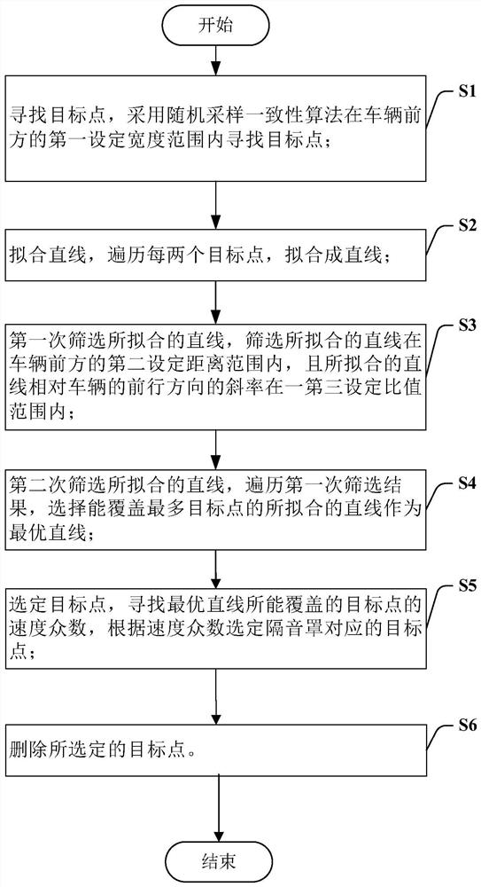
Step S1, find the target point, using a random sampling consensus algorithm to find the target point within the first set width range in front of the vehicle;
Step S2, fit a straight line, traverse each of the two said target points, fit a straight line;
Step S3, the fitted straight line is screened for the first time, the fitted straight line is screened within the second set distance in front of the vehicle, and the slope of the fitted straight line relative to the forward direction of the vehicle is within a third set ratio;
Step S4, the second screening of the fitted line, iterating through the first screening results, selecting the fitted line that can cover the most of the target points as the optimal straight line;
Step S5, select the target point, find the velocity mode of the target point that the optimal straight line can cover, and select the target point corresponding to the acoustic enclosure according to the velocity mode;
Step S6, delete the selected target point.
According to one embodiment of the present invention, in step S1, the first setting width is perpendicular to the central axis of the vehicle, and the first setting width is 1m ~ 2m.
According to one embodiment of the present invention, in step S3, the second set distance is 10m ~ 30m.
According to one embodiment of the present invention, in step S3, the third set ratio is less than 8 and greater than -8.
According to one embodiment of the present invention, in step S4, if the distance from the target point to the fitted straight line is less than a set threshold, then the target point can be covered by the fitted straight line.
According to one embodiment of the present invention, before performing step S5, a state machine is employed to reduce the randomness of the straight-line fitting.
According to one embodiment of the present invention, the state machine adopts a counter, the counter sets a threshold value, and the execution steps of the state machine comprise:
Step T1, the state machine finds the optimal line in the fitted line, and if the optimal line is found, the counter is added by 1;
Step T2, determine whether the counter reaches the set threshold, if not, return to step S1; Otherwise proceed to the next step;
Step T3, determine that the target point is valid.
According to one embodiment of the present invention, in step S5, the velocity mode is obtained by finding the target point having the same speed, or by the speed of the vehicle.
According to one embodiment of the present invention, in step S5, in the process of finding the velocity mode of the target point, the target point conforming to the velocity majority reaches a set number, then the velocity mode obtained is valid.
The present invention also provides a removal device for road acoustic enclosures, suitable for vehicle radar, comprising:
The search module uses a random sampling consensus algorithm to find a target point within the first set width range in front of the vehicle radar;
the straight-line fitting module, receiving the target point found by the search module, traversing each of the two target points, fitting a straight line;
the first screening module, receiving the straight line fitted by the straight line fitting module, screening retaining the straight line within the second set distance in front of the vehicle, and the slope of the fitted straight line relative to the forward direction of the vehicle is within a third set ratio;
the second screening module, which receives the line screened by the first screening module, selects the fitted straight line that can cover the most of the target point as the optimal straight line;
Select the target point module, find the velocity mode of the target point covered by the optimal straight line, and select the target point corresponding to the acoustic enclosure according to the velocity mode;
Delete Module, deletes the target point selected by the Selected Target Point module.
The present invention provides a removal method for road sound insulation cover and a removal device thereof, which can distinguish and remove the road sound insulation cover, so that the normal target track in front of the vehicle can be retained.
Specific embodiment
In order to make the above objects, features and advantages of the present invention more obvious and easy to understand, the following in conjunction with the accompanying drawings of the present invention in detail in detail.
Many specific details are set forth in the following description in order to fully understand the present invention, but the present invention may also be implemented in other ways different from those described herein, so the present invention is not limited by the specific embodiments disclosed below.
As indicated in this application and the claims, the terms "one", "a", "a" and/or "the" do not refer specifically to the singular and may include the plural, unless the context expressly indicates an exception. In general, the terms "including" and "including" only imply the inclusion of clearly identified steps and elements, and these steps and elements do not constitute an exclusive list, methods or devices may also contain other steps or elements.
In detailing embodiments of the present application, for ease of illustration, the profile view indicating the device structure will not be partially enlarged according to the general proportion, and the schematic diagram is only an example, which should not limit the scope of protection of the present application. In addition, the actual production should include three-dimensional spatial dimensions of length, width and depth.
For ease of description, spatial relationship words such as "below", "below", "below", "below", "above", "above", etc. may be used herein to describe the relationship of one element or feature shown in the drawings to other components or features. It will be understood that these spatial relationship words are intended to include directions other than those depicted in the drawings of the device in use or in operation. For example, if the device in the drawing is flipped, the orientation of the component described "below" or "below" or "below" other components or features will be changed to "above" the other components or features. Thus, the exemplary words "below" and "below" can encompass both up and down directions. Devices may also have other orientations (90 degrees of rotation or other orientations), so the spatial relationship descriptors used here should be interpreted accordingly. Further, it will be understood that when a layer is referred to as "between" between two layers, it may be the only layer between the two layers, or there may also be one or more layers in between.
In the context of the present application, the structure of the first feature described "above" the second feature may include embodiments of the first and second features forming as direct contact, and may also include additional embodiments of feature formation between the first and second features, such that the first and second features may not be in direct contact.
Since the acoustic enclosure is usually set directly above the road, its shape is mostly semicircular tubular, but the acoustic enclosure cannot be distinguished from ordinary targets from the shape displayed by the vehicle radar. The acoustic enclosure is not like a fence, and it can be seen from the appearance that it is neatly straight. Therefore, the characteristics of the acoustic enclosure can only be found through the echo data characteristics of the acoustic enclosure. Due to the pitch angle of the radar and the beam width of the radar, the radar wave has echoes at only the top point of the semicircular tubular acoustic enclosure, and these points form an elongated straight line according to which the acoustic enclosure data can be filtered. Define these points that make up an elongated line as target points.
FIG 1 is a flowchart of a removal method for a road sound enclosure in an embodiment of the present invention. FIG 2 is a brief schematic diagram of one embodiment of the present invention. As shown in the figure, a method for removing road acoustic covers, suitable for vehicle radar, comprising:
Step S1, to find the target point, the random sampling consensus algorithm is used to find the target point within the first set width range in front of the vehicle. The target point is the echo signal received by the vehicle's radar from the obstacle ahead. Referring to Figure 2, the X-axis direction is the horizontal direction of the front of the vehicle, and the Y-axis direction is the central axis of the vehicle. Look for the target point 201 within the first set width L1.
Step S2, Fit Straight Line, traverse every two target points, Fit Straight Line. Specifically, it is necessary to traverse the combination of each of the two target points to fit the straight line, and then find the global optimal solution, that is, the most suitable straight line.
Step S3, the fitted straight line is screened for the first time, so that the fitted straight line is within the second set distance in front of the vehicle, and the slope formed by the fitted straight line and the forward direction of the vehicle is within the range of a third set ratio. Here, the second set distance and the third set ratio are used as constraints to select the fitted straight lines that meet the requirements, which is equivalent to removing those lines that are not fitted by the acoustic enclosure. Refer to Figure 2 to find a fitted line within the second set distance L2.
Step S4, the second screening of the fitted line, iterating through the first screening result, selecting the fitted line that covers the most target points as the optimal straight line.
Step S5, select the target point, find the velocity mode of the target point 201 covered by the optimal straight line, and select the target point 201 corresponding to the acoustic enclosure according to the velocity mode.
Step S6, delete the selected target point 201, which is equivalent to deleting the trajectory of the acoustic enclosure on the vehicle radar.
Preferably, in step S1, the first set width is 1m~2m. Since the sound enclosure only has data in front of the vehicle radar, when fitting the straight line, it is only necessary to find the target point 201 directly in front, that is, in front of the vehicle radar, which is equivalent to extracting the straight line within 0.5~1 meters of the left and right of the vehicle head position along the central axis, so that it will not be wrongly fitted to other obstacles such as fences. Easy to understand, referring to Figure 2, the central axis of the vehicle is the Y axis, and the vehicle travels along the Y axis. In the width range of 1m on the left and right of the Y axis, look for the target point 201. The first set width L1 direction is perpendicular to the Y axis and is consistent with the width direction of the body. In addition, this method can effectively reduce the calculation amount of random sampling consensus algorithm and improve the removal efficiency.
Preferably, in step S3, the second set distance L2 is 10m~30m. Since the fence on the side of the road close to the vehicle radar also meets the fitting straight line and can also meet other conditions, it is ensured that the target point 201 corresponding to the fence is not mistakenly deleted according to the difference between the fence and the sound insulation hood. After actual observation, it was found that the acoustic enclosure appeared more than ten meters in front of the radar and began to form a straight line, while the fence formed a straight line from the horizontal position directly left or right of the vehicle radar. Therefore, the starting point of the straight line of the control fitting sound enclosure is selected as a range of 10 meters to 30 meters, which can effectively reduce the situation of accidental deletion of fences. Control the area of 10 meters to 30 meters, because the vehicle radar has a pitch angle, such as when the pitch angle of the radar is between -15 degrees and 15, the 3-meter-high sound insulation cover, the detection distance is about 12 meters, so only the fitted straight line that begins to appear outside 10 is likely to be a sound enclosure, and the fitted straight line that appears within 10 meters is most likely to be a fence within the front range.
Preferably, in step S3, the third set ratio is less than 8 and greater than -8. When fitting a straight line, because the vehicle can only drive along the front of the elevated in the elevated sound enclosure, there will be no turning and U-turn, so the slope of the control fitting line and the vehicle forward direction is less inclined in the range, and the slope range is less than 8 and greater than -8, so that the target point 201 fitted straight line corresponding to the sound insulation cover can be correctly found.
Preferably, in step S4, if the distance from the target point 201 to the fitted line is less than a set threshold, then the target point 201 can be covered by the fitted line. Or that the target point 201 belongs to the fitted straight line. The optimal line is to find a fitted line such that the target point 201 belonging to the line is the most.
Preferably, a state machine is employed to reduce the randomness of the straight-line fitting before performing Step S5. Since the effect of straight-line fitting will fluctuate due to the echo of vehicle radar, a state machine is used to reduce the randomness of straight-line fitting and increase the credibility of straight-line fitting.
Preferably, the state machine uses a counter, which sets the threshold, and the steps performed by the state machine include:
Step T1, the state machine finds the optimal line in the fitted line, and if the optimal line is found, the counter adds 1;
Step T2, determine whether the counter reaches the set threshold, if not, return to step S41; Otherwise proceed to the next step;
Step T3, determine that the target point 201 is valid.
Since the effect of straight-line fitting will fluctuate due to the echo of vehicle radar, the state machine method is used to reduce the randomness of straight-line fitting and increase the credibility of straight-line fitting. The state machine adopts the counting method, if the current time can find the optimal straight line, then the counter is added to one, after a number of time periods, when the counter reaches the number of thresholds, it is judged that the vehicle radar is now in the acoustic enclosure environment, then the target point 201 that forms the fitted straight line is effective, and the subsequent operation of filtering out the soundproof hood trajectory can be carried out. In addition, after continuously and stably filtering out the trajectory of the acoustic enclosure many times, the state machine occasionally if the optimal straight line is not found, according to the principle of the state machine, the straight line that will be fitted according to historical information is used to eliminate the trajectory of the acoustic enclosure. The use of state function can ensure that the sound enclosure trajectory can be stably filtered out in the case of missing data, and can also ensure that it is not filtered out when there is occasional false optimum.
Preferably, in step S5, the velocity mode is obtained by looking for a target point 201 with the same speed, or by the vehicle's speed. If the vehicle's speed is known, the speed mode can be set to an absolute speed of zero.
Preferably, in step S5, in the process of finding the velocity mode of the target point 201, the target point 201 that conforms to the velocity majority reaches a set number, then the velocity mode is valid. Preferably, the number of settings is 4. It is easy to understand, when finding the velocity majority, only when the target point 201 that satisfies the velocity majority reaches a certain number, the velocity majority is used to select the target point 201 corresponding to the echo of the acoustic enclosure, that is, the target point 201 that determines that the velocity of the target point 201 is similar to the velocity majority is considered to be generated by the acoustic enclosure, and then the target point 201 is deleted to avoid the target of normal movement in front of it being deleted.
The present invention also provides a removal device suitable for road noise enclosures of vehicle radar. FIG 3 is a schematic diagram of the structure of a road sound enclosure removal device in an embodiment of the present invention. As shown in the figure, the removal device 300 mainly includes a search module 301, a straight line fitting module 302, a first screening module 303, a second screening module 304, a selected target point module 305 and a deletion module 306.
wherein the search module 301 adopts a random sampling consensus algorithm to find the target point 201 within the first set width L1 range in front of the vehicle radar.
The straight-line fitting module 302 is used to receive the target point 201 found by the search module 301, traverse every two target points 201, fit a straight line.
The first screening module 303 receives the straight line fitted by the straight line fitting module 302, the screening retention line is within the range of the second set distance L2 in front of the vehicle, and the slope of the fitted straight line relative to the forward direction of the vehicle is within a third set ratio.
The second screening module 304 receives the first screening module 303 filtered straight line, and selects the fitted straight line that can cover the maximum target point 201 as the optimal straight line.
The selected target point module 305 is used to find the velocity mode of the target point 201 covered by the optimal straight line, and selects the target point 201 corresponding to the acoustic enclosure according to the velocity mode.
Delete module 306 is used to delete the selected target point module 305 selected target point 201 on the radar.
Although the present invention has been described with reference to the current specific embodiment, but ordinary skill in the art should realize that the above embodiments are only used to illustrate the present invention, and may make various equivalent changes or replacements without departing from the spirit of the present invention, therefore, as long as the substance of the present invention within the spirit of the present invention of the changes, variants will fall within the scope of the claims of the present application.


 400-4929-0909
 contact@catarc.com.cn

