Technical field
This utility model belongs to the technical field of automotive interior components and relates to a door interior panel.
Background Technology
As the automotive industry accelerates, consumers have higher demands for the appearance of interior parts, and refined parts have become a key factor in enhancing car brands. Currently, there is a wide variety of sedans from various brands on the market, and the interior decoration layouts are distinctive. However, the interior door panels mostly include switch panel modules, map pockets inside the doors, and door switches.
Existing map bag designs have obvious structural flaws: as a standalone decorative item, the map bag usually requires a clearance hole on the interior panel body first, then fixed to the interior panel body by welding or snapping back to create storage space. This split design causes noticeable step differences on the inner surfaces of the interior panels, which not only affect the overall aesthetics but more importantly, make it easy for occupants to touch the step differences when storing items, causing inconvenience during use. Moreover, this traditional structure faces complex assembly processes and high manufacturing costs, making it difficult to meet Hyundai's dual requirements for interior refinement and cost control.
Therefore, the map pocket structure on the door trim panel needs to be redesigned to reduce design costs while enhancing the refinement of the door trim panels and improving the product's market competitiveness.
Summary of the utility model
In view of this, this utility model provides a door interior trim panel, which, by integrating and installing bosses on the interior panel body and cooperating with the cover plate to form a storage chamber, avoids the step difference caused by traditional split designs, simplifies the assembly process, and offers advantages such as simple structure, easy assembly, high aesthetics, and low cost.
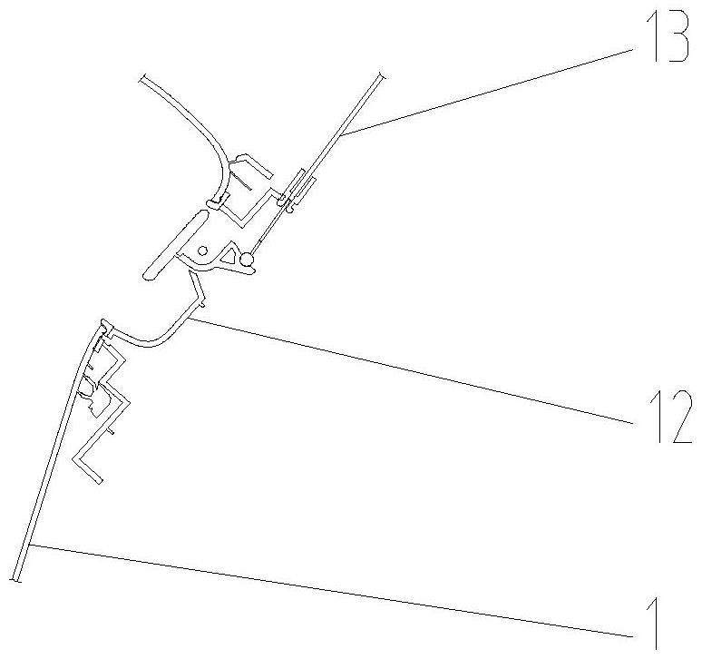
This utility model discloses a car door interior panel, comprising an interior panel body. The interior panel body integrates a mounting boss on the side facing the interior direction. The installation boss has a notch with an opening facing upward in the vehicle height direction. The mounting boss is provided with a cover plate to enclose the installation boss along the width of the vehicle body. After being fixed and connected to the installation boss, the cover plate together forms a storage chamber at the notch position.
Furthermore, the cross-sectional projection of the mounting boss along the vehicle width direction is U-shaped, and includes a speaker mounting end corresponding to the preset position of the body speaker. The speaker mounting end is provided with a speaker mounting hole, and the cover plate is provided with a speaker cover mounting section at the corresponding position of the speaker mounting hole.
Furthermore, the interior panel body integrates a speaker mounting ring at the position of the speaker mounting hole.
Furthermore, a speaker cover is connected and fixed at the mounting part.
Furthermore, the horn cover has mounting feet formed by bending, which are connected and fixed to the horn-shaped mounting part via the mounting feet.
Furthermore, several connecting parts are arranged on the peripheral edge of the mounting boss for fixing and connecting to the cover plate.
Furthermore, the connecting part includes a locking hole for clamping and fixing to the cover plate and a connecting seat for welding and fixing to the cover plate.
Furthermore, the mounting boss is formed by the interior trim panel body protruding outward along the width direction of the vehicle body.
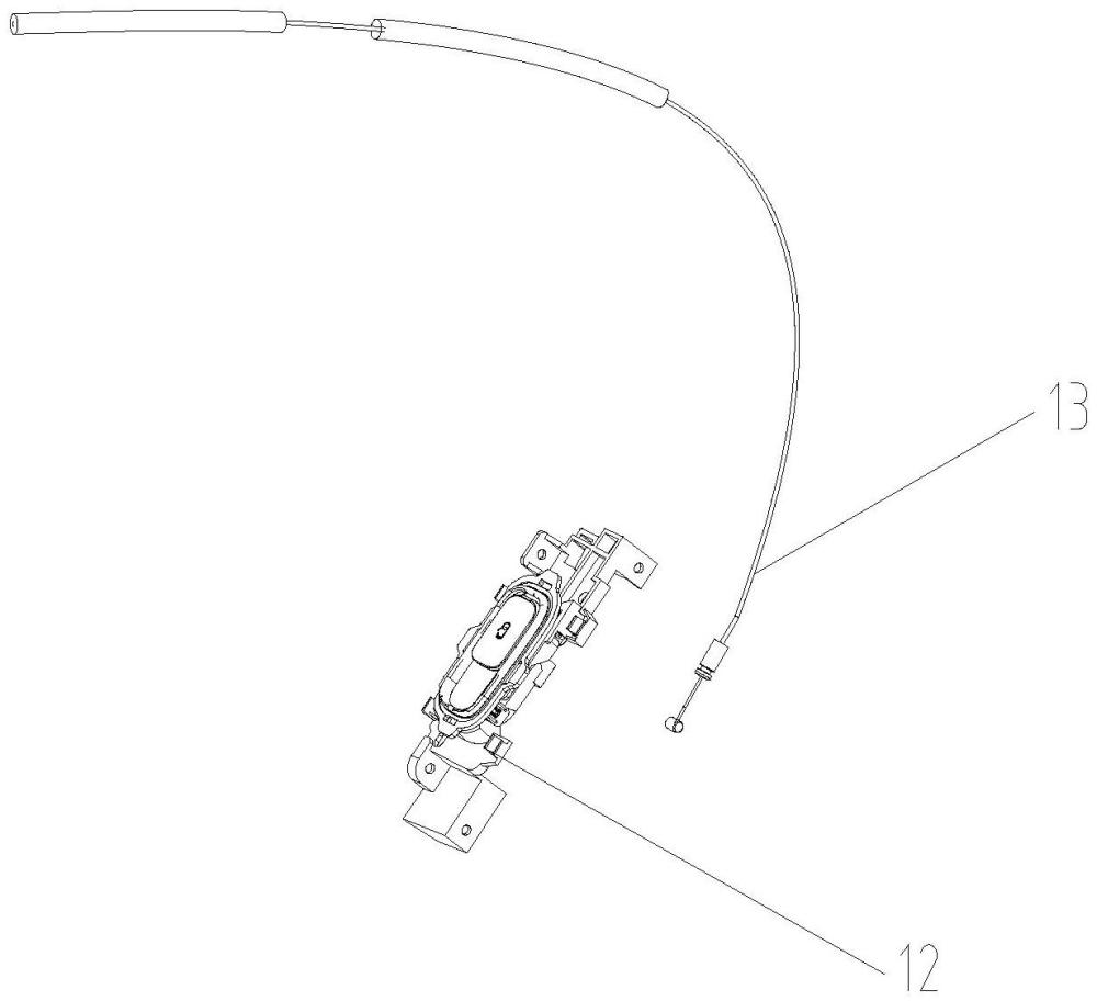
Furthermore, the interior panel body is also equipped with a door lock emergency switch located above the storage chamber, which is connected and cooperated with the trigger end of the car door lock via a cable.
Beneficial effects of this utility model:
This utility model provides a car door interior trim panel, which, by integrating and installing bosses on the interior panel body and cooperating with the cover plate to form a storage chamber, avoids the step difference caused by traditional split designs, simplifies the assembly process, and features a simple structure, easy assembly, high aesthetics, and low cost; Furthermore, by integrating the speaker ring into the interior panel body, it reduces the need for separate mold development for the speaker ring, thereby lowering costs; By adding a metal horn cover to the cover and fixing it with bent mounting feet, the interior panel feels more refined.
Description of the drawings
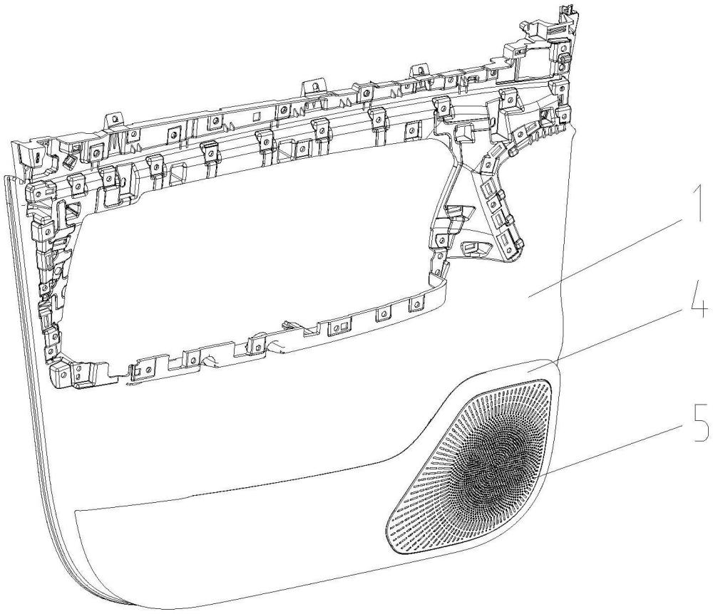
Figure 1 is a front schematic diagram of the structural structure of the door interior panel in this utility model;
Figure 2 is a schematic diagram of the rear side of the door trim panel structure in this utility model;
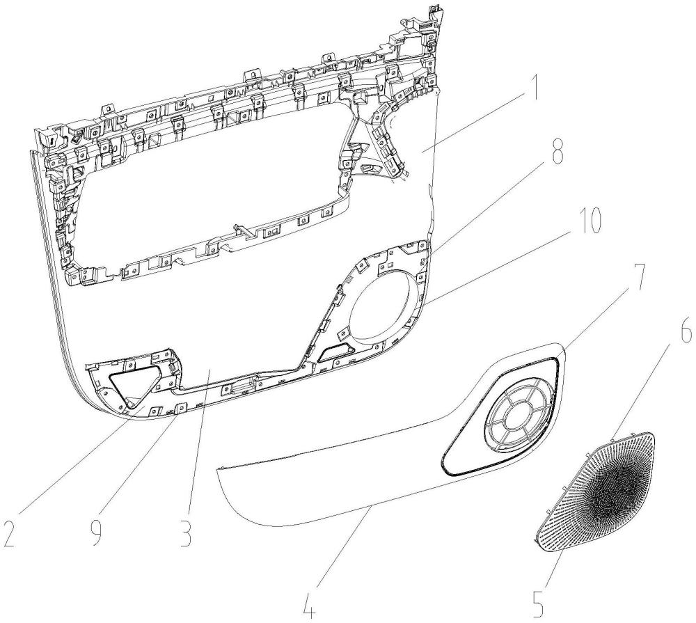
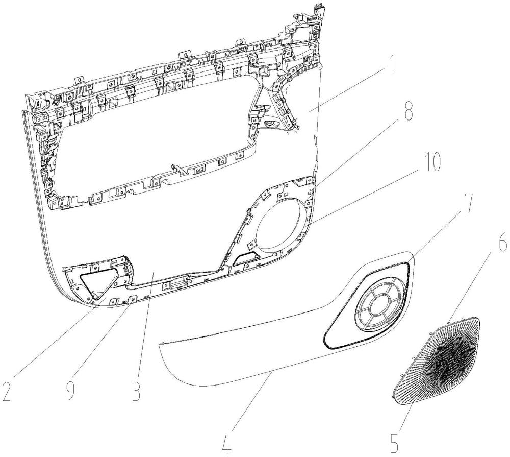
Figure 3 is a schematic diagram of the structural explosion of the door trim panel in this utility model;
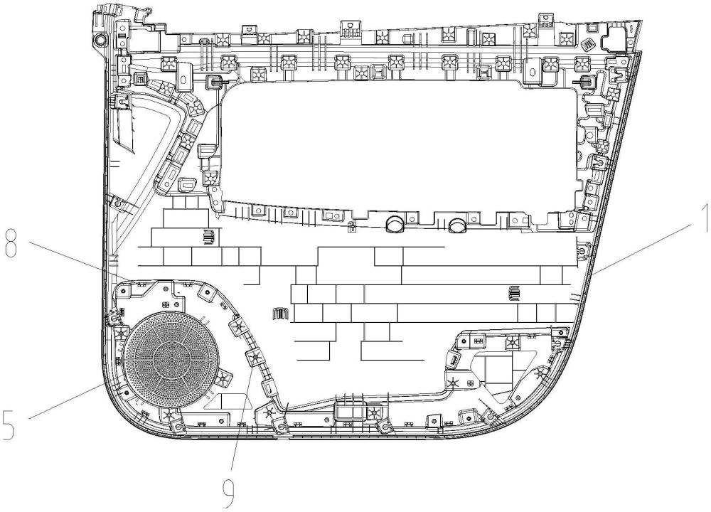
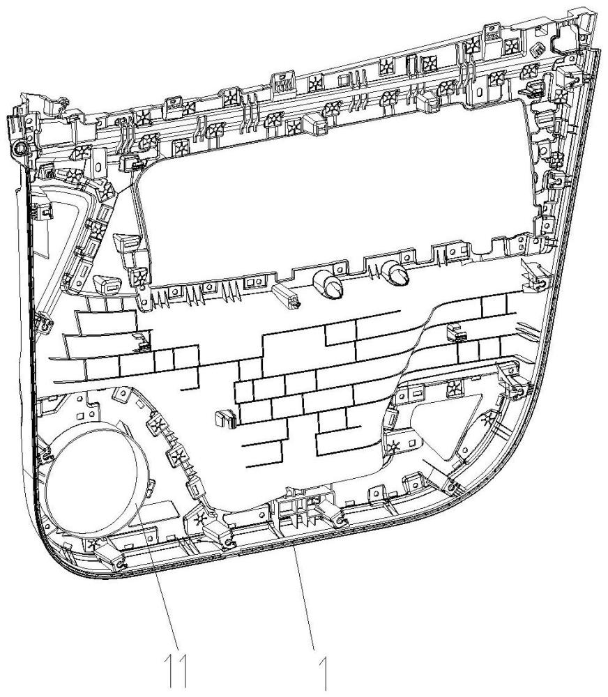
Figure 4 is a schematic diagram of the rear side of the interior panel body structure in this utility model;
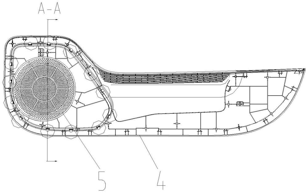
Figure 5 is a schematic diagram of the back side of the cover plate structure in this utility model;
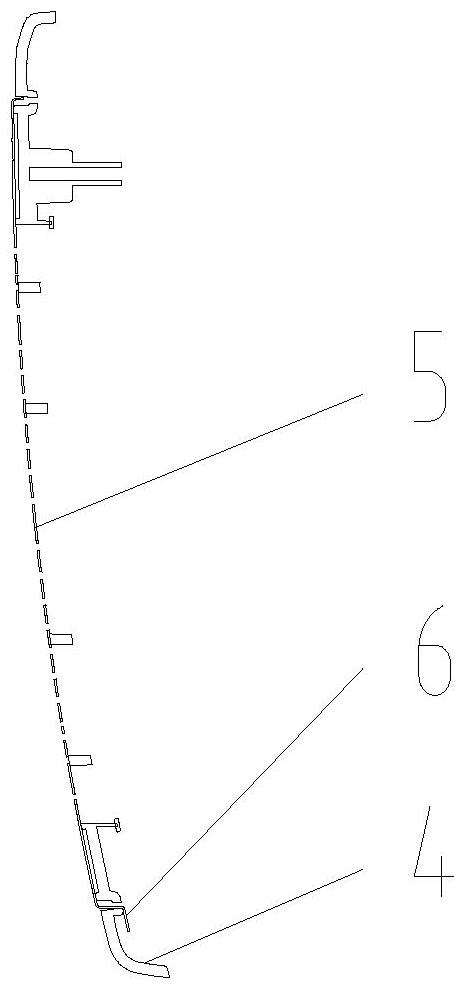
Figure 6 is a sectional view of A-A from Figure 5;
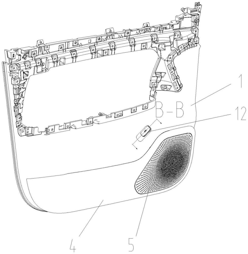
Figure 7 is a front schematic diagram of the structural structure of the door interior trim panel in another embodiment of this utility model;
Figure 8 is a sectional view of B-B from Figure 7;
Reference numerals in the drawings: interior panel body 1, mounting boss 2, notch 3, cover plate 4, speaker cover 5, mounting foot 6, speaker cover mounting section 7, clip hole 8, connector base 9, speaker mounting hole 10, speaker mounting ring 11, door lock emergency switch 12, guy cable 13.
Specific embodiments
It should be noted that in the description of this specification, terms such as "upper," "lower," "top," "bottom," "inner," "outer," "axial," "radial," "circumferential," and other indicated orientations or positional relationships are based on the orientation or positional relationships shown in the drawings, and are intended solely to facilitate the description and simplify the description of this utility model, not to indicate or imply that the device or component must have a specific orientation, be constructed and operated in a specific orientation, and therefore should not be construed as limiting the present utility model.
As shown in the figures, an embodiment of this utility model discloses a car door interior panel, which includes an interior panel body 1. The interior panel body 1 integrates a mounting boss 2 on the side facing the interior direction. The mounting boss 2 has a notch 3 with an opening facing upward in the vehicle height direction. The mounting boss 2 is provided with a cover plate 4 to wrap the installation boss 2 in the width direction of the vehicle body. After being fixed and connected to the installation boss 2, the cover plate 4 is connected and fixed together at the notch 3 to form a storage chamber; The interior panel body 1 serves as the main load-bearing structure for the door interior and is generally made using injection molding technology. Therefore, by adding the mold design stage to the mounting boss 2, the installation boss 2 and the interior panel body 1 are integrally molded. The notch 3 is arranged at the upper part of the installation boss 2 at the height of the vehicle body, making it easier for occupants to access and store items. The cover plate 4 can be fixed to the mounting boss 2 by snap-on connection or ultrasonic welding. The cover plate 4 material can be selected as the same material as the interior panel body 1 to ensure appearance consistency. This technical solution integrates the installation boss 2 with the interior panel body 1, avoiding the step difference issues associated with traditional split map bag installation; The cover plate 4 and the installation boss 2 cooperate to form a closed storage chamber, ensuring storage functionality while improving the flatness of the interior surface; Among them, the integrated installation boss 2 structure eliminates assembly errors caused by traditional welding or snap-fit processes, making the transition around the storage chamber smoother. This design significantly enhances the refinement and comfort of the interior surface while maintaining storage functionality.
In this embodiment, the cross-sectional projection of the mounting boss 2 along the vehicle width direction is U-shaped, and includes speaker mounting ends corresponding to preset body speaker positions; Combined with Figure 3, the cross-sectional projection of the installation boss 2 along the width direction of the vehicle body is U-shaped, sequentially forming an upward-opening notch 3 structure, which facilitates the formation of a storage chamber together with the cover plate 4; At one of the lateral sides of the notch 3, a speaker mounting end is provided, and the speaker mounting end position is set according to the speaker positions preset on the vehicle body.
In this embodiment, the speaker mounting end is provided with a speaker mounting hole 10, and the interior panel body 1 integrates a speaker mounting ring 11 at the position of the speaker mounting hole 10; The speaker mounting hole 10 is used to fix the body speaker. Its diameter matches the speaker's outer diameter and can be round, square, or other geometric shapes. The speaker mounting ring 11 is integrally injection-molded with the interior panel body 1, aligning its inner diameter with the speaker mounting hole 10, and extending the outer diameter to the back of the interior panel body 1 to form an annular support surface. This technical solution integrates speaker mounting ends with mounting holes on the interior panel body 1 and synchronously forms the speaker mounting ring 11, achieving modular design of the speaker mounting structure, reducing the need for separate mold development for the speaker ring and lowering costs; Compared to traditional split-type installation structures, this solution eliminates the assembly gap and step differences caused by installing speaker brackets separately. At the same time, the integrated installation ring enhances structural strength, preventing abnormal noise caused by speaker vibration. The ring-shaped support surface evenly distributes the speaker's weight, preventing local deformation of the interior panel.
In this embodiment, the cover plate 4 is equipped with a speaker cover mounting section 7 at the corresponding position of the speaker mounting hole 10, and a speaker cover 5 is connected and fixed at the speaker mounting part 7; The horn cover 5 has a bent mounting foot 6 and is fixed to the horn-shaped mounting part via the mounting foot 6. Referring to Figure 3, the speaker cover mounting section 7 is an annular mesh cover structure coaxially arranged on the cover plate 4 and the speaker mounting hole 10. The speaker cover mounting part 7 and cover plate 4 can be manufactured integrally by injection molding to reduce assembly complexity. By arranging the speaker cover mounting section 7 on the cover plate 4, the speaker cover 5 can be directly mounted on the cover plate 4 rather than the interior panel body 1, so that during later interior assembly, the cover plate 4 and speaker cover 5 can be assembled as a whole in advance. The entire assembly is onto the interior panel body 1 to reduce assembly steps; The speaker cover 5 is made of metal, and its peripheral edges have a mounting foot 6 structure formed by bending, thereby achieving a reliable connection between the speaker cover 5 and the mounting section, solving the problem of abnormal noises and loosening during traditional installation of the speaker cover 5, and improving the acoustic stability of the audio system.
In this embodiment, several connecting parts are arranged on the peripheral edge of the mounting boss 2 for fixing and connecting to the cover plate 4; The connecting section includes a locking hole 8 for clamping and fixing to the cover plate 4, and a connecting seat 9 for welding and fixing to the cover plate 4. The locking hole 8 can form a through-hole structure by stamping along the periphery of the mounting boss 2, with the hole diameter forming an interference fit with the latch protrusion on the cover plate 4; The connecting seat 9 may adopt a boss structure integrally molded with the mounting boss 2, with a welding surface on top. It is fused and fixed to the cover plate 4 by ultrasonic welding or hot plate welding. Furthermore, the connecting seat 9 can also be designed as a metal insert with threaded holes, and can be detachably connected to the cover plate 4 via screws. This technical solution effectively solves the problem of insufficient connection strength between cover plate 4 and mounting boss 2 by setting up a dual fixing structure for snapping and welding; The snap-fit structure enables quick pre-positioning, while the welded structure provides final fixation assurance. The synergy of both avoids the risk of loosening that may arise with a single connection method; The structural stability of the storage chamber formed between the mounting boss 2 and cover plate 4 is significantly improved, avoiding abnormal noises or detachment caused by connection failure.
In this embodiment, the interior panel body 1 is also equipped with a door lock emergency switch 12 located above the storage chamber, which is connected and cooperated with the door lock trigger end via a cable 13; The door lock emergency switch 12 can adopt a press-type or knob structure, with the specific installation position adjusted according to the internal spatial layout of the door; Cable 13 may use metal steel wire rope or nylon guy wire, with one end mechanically linked to the emergency switch and the other end extending to the door lock mechanism. Since the storage chamber is enclosed together by the installation boss 2 and cover plate 4, the space above it is reasonably utilized to arrange the emergency switch assembly; Therefore, when the electronic door lock fails, occupants can unlock the door by operating the mechanical emergency switch on the interior panel. The connection and cooperation between the door lock emergency switch 12, the cable 13, and the door lock are based on prior art and will not be discussed here. This design integrates the traditionally scattered emergency mechanisms into the interior panel functional area, maintaining the flatness of the interior surfaces while ensuring the doors can be opened normally in emergencies.
Finally, it should be noted that the above embodiments are only intended to illustrate the technical solutions of the present utility model and not to limit them. Although the utility model has been described in detail with reference to preferred embodiments, those skilled in the art should understand that modifications or equivalent substitutions of the technical solutions of this utility model can be made without departing from the purpose and scope of the technical solutions of this utility model, and all such actions should be included within the scope of the claims of the present utility model.
Door interior panels










 400-4929-0909
 contact@catarc.com.cn