Utility model content
In view of this, the purpose of the utility model is to provide a car seat massage leg rest assembly, which has a simple structure and has a good massage effect, which is conducive to meeting the user's needs for deep leg massage.
In order to achieve the above purpose, the utility model provides the following technical scheme: an automobile seat massage leg rest assembly, comprising a leg support plate and two sets of massage mechanisms arranged on the leg support plate for occupant leg massage, and the massage mechanism comprises: a rotating shaft that can be driven to rotate and is arranged on the leg support plate; drive mechanism for driving the rotation of the rotating shaft; the first massage assembly, comprising two sets of first massage arms respectively arranged at both ends of the axis of the rotating shaft, and the first massage arm is arranged on the rotating shaft in such a way that it can swing back and forth in the direction of the width of the body driven by the rotating shaft; The second massage assembly comprises two sets of second massage arms corresponding to each end of the axis of the rotating shaft, and the second massage arm is arranged on the rotating shaft in such a way that it can swing back and forth in the direction of the length of the body driven by the rotating shaft.
Further, the two ends of the rotating shaft are respectively provided with a first eccentric shaft sleeve fixed relative to the rotating shaft, the first eccentric shaft sleeve is provided with an eccentric shaft segment arranged at a set angle with the axis of the rotating shaft, the first massage arm is arranged on the eccentric shaft segment of the first eccentric shaft sleeve on the corresponding side, the leg support plate is provided with a first limiting groove arranged along its own length, and the first massage arm is provided with a sliding first limiting column in the first limiting groove.
Further, the two ends of the rotating shaft are respectively provided with a second eccentric shaft sleeve fixed relative to the rotating shaft, the second eccentric shaft sleeve is located on the inside of the first eccentric shaft sleeve of the corresponding side, the second massage arm is arranged on the second eccentric shaft sleeve of the corresponding side, the leg support plate is provided with a second limit groove arranged in the direction of its own width, and the second massage arm is provided with a second limit column that slides to fit the second limit groove.
Further, the first massage arm of the two is set face to face, and the top of the first massage arm is expanded outward.
Further, the working surface of the first massage arm is provided with a massage cushion with a heating function.
Further, the second massage arm is arranged opposite each other, and the second massage arm is L-shaped structure.
Further, the top of the second massage arm is inherently equipped with a massage head.
Further, the leg support plate is provided with a recessed recessed part, and the driving mechanism comprises a drive motor and a transmission assembly arranged in the recessed part; The transmission assembly comprises a worm fixed as one piece with the output shaft of the driving motor, a first gear meshed with the worm, a second gear fixed as one with the first gear, and a third gear fixed on the rotating shaft and meshed with the second gear.
Further, the upper cover of the recessed part is closed with an upper cover plate, and the upper cover plate covers the drive motor and the transmission assembly in the recessed part.
Further, it also includes a face cover set on the leg support plate, the face cover wraps two sets of massage mechanisms, and a filling layer is provided between the face cover and the leg support plate.
Compared with the prior art, the beneficial effects of the present utility model are as follows:
The car seat massage leg rest assembly provided by the utility model has a simple structure and has a good massage effect, which is conducive to meeting the user's needs for deep leg massage; Specifically, leg massage can be achieved by driving two sets of massage components to swing back and forth through a rotating axis, with a simple structure and relatively low cost. Because one of the two sets of massage components swings back and forth in the direction of the width of the body, and the other swings back and forth in the direction of the length of the body, it can achieve a massage effect similar to human hand tiger's mouth massage, which can directly and effectively massage the muscle groups in depth and have a better massage effect.
The other advantages, objectives and features of the utility model will be elaborated to some extent in subsequent specifications, and to some extent will be obvious to persons skilled in the field based on the following investigation and research, or can be taught from the practice of the utility model. The objectives and other advantages of the utility model can be realized and obtained by the following specification.
Specific embodiment
The following illustrates the embodiment of the utility model through specific specific examples, and personnel skilled in the field can easily understand the other advantages and effects of the utility model from the contents disclosed in this specification. The utility model can also be implemented or applied through different specific embodiments, and the details in this specification can also be modified or changed based on different views and applications, without deviating from the spirit of the utility model. It should be noted that in the following embodiments, the "first", "second" and "third" do not represent an absolute distinction between structure and/or function, nor do they represent the order of execution, but are only for the convenience of description. It is understandable that the width direction of the body in the following is the horizontal direction of the body, and the direction of the length of the body is also the longitudinal direction of the body; Same as the traditional automobile leg support arrangement structure, when the leg support 1 is arranged, the length direction of the leg support 1 is consistent with the lateral direction of the body.
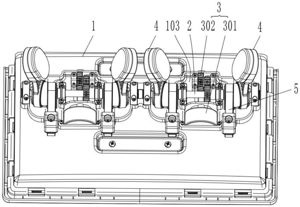
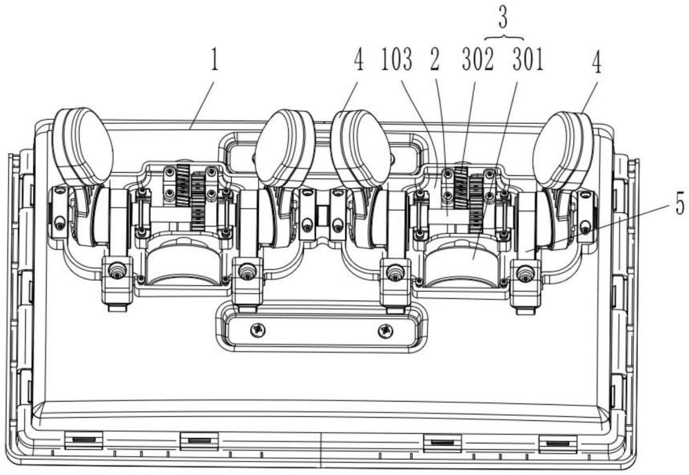
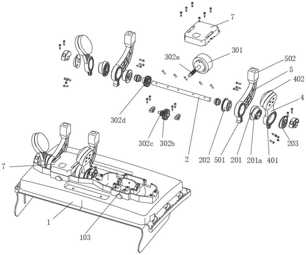
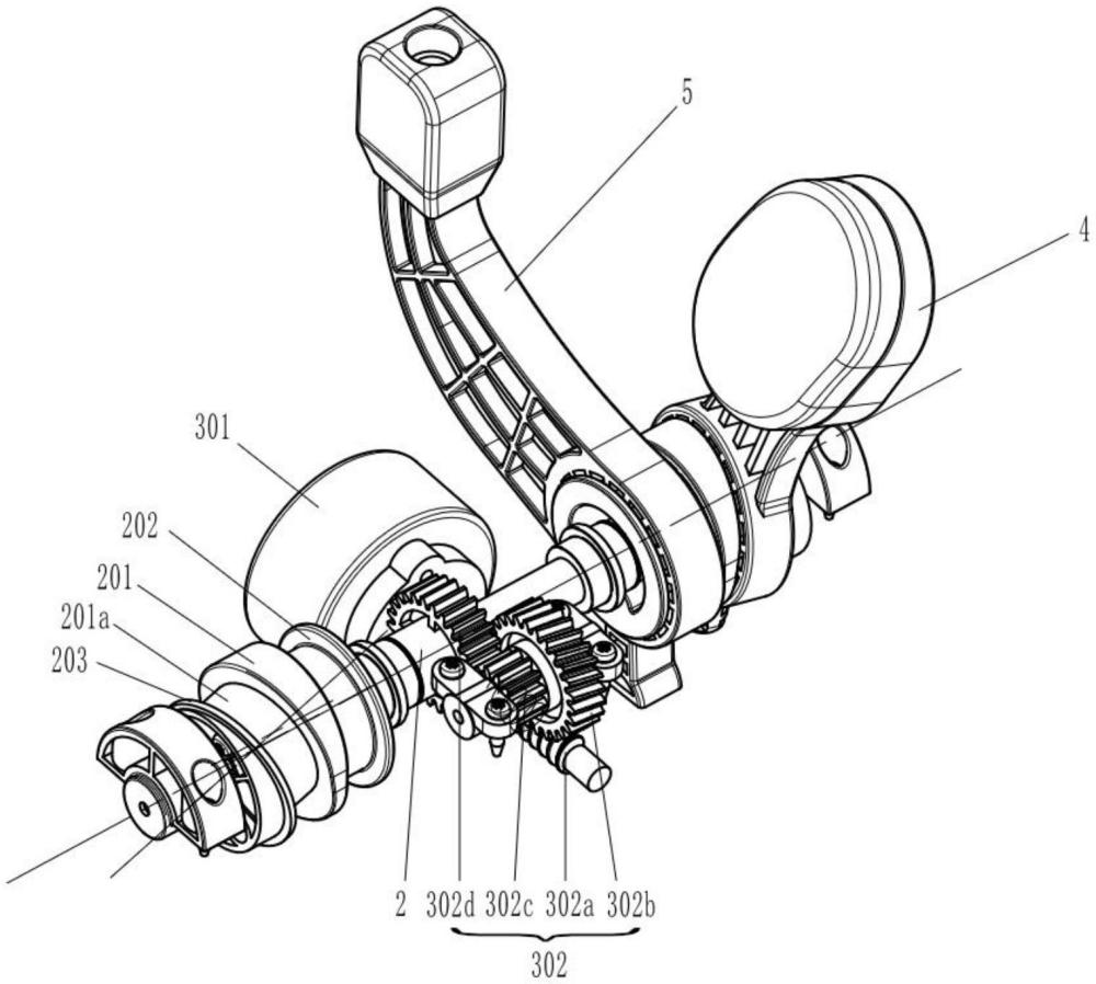
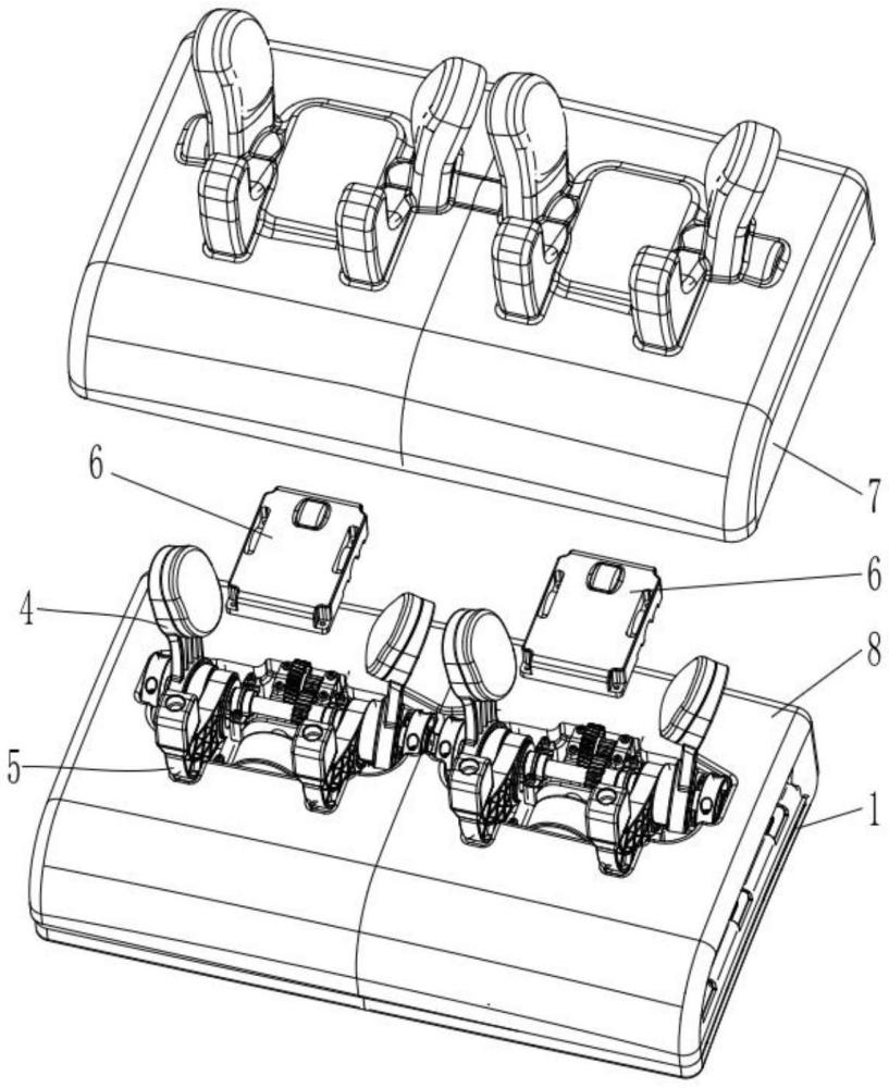
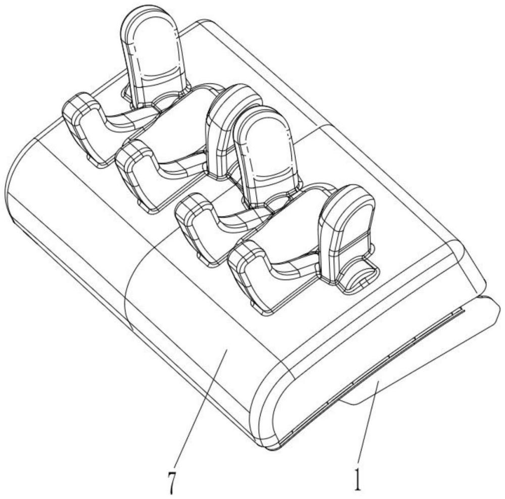
Refer to FIG. 1-6, in this embodiment, an automobile seat massage leg rest assembly is disclosed, comprising a leg support plate 1 and two sets of massage mechanisms arranged on the leg support plate 1 for occupant leg massage, the massage mechanism comprises a rotating shaft 2, a driving mechanism 3, a first massage assembly and a second massage assembly, wherein: a rotating shaft 2 can be driven to rotate on the leg support plate 1, specifically, the rotation shaft 2 is installed on the leg support plate 1 through a plurality of bearings; The drive mechanism 3 is used to drive the rotation of the rotating shaft 2, it is understood that the driving mechanism 3 mostly uses the drive motor as the driving source, and the output end of the driving mechanism 3 is connected with the rotation shaft 2 to drive the rotating shaft 2 to rotate; The first massage assembly comprises two sets of first massage arms 4 corresponding to each end of the axis of rotation shaft 2, and the first massage arm 4 is arranged on the rotating shaft 2 in such a way that it can swing back and forth in the direction of the width of the body under the driving force of the rotating shaft 2, and it is understood that a space for placing the occupant's legs can be formed between the two groups of first massage arms 4, and a patting massage on both sides of the occupant's legs is formed in the process of the first massage arm 4 swinging laterally and reciprocatingly; The second massage assembly comprises two sets of second massage arms 5 corresponding to the two ends of the axis of rotation shaft 2, and the second massage arm 5 is arranged on the rotating shaft 2 in such a way that it can swing back and forth in the direction of the length of the body driven by the rotating shaft 2, and it is understood that a space for placing the occupant's legs can be formed between the two sets of second massage arms 5, and in the process of longitudinal reciprocating swing of the second massage arm 5 in the direction of the front and back and up and down directions of the occupant legs ( The front and rear directions and the up and down directions here refer to the front and rear directions and the up and down directions of the body); For the leg support plate 1, it is consistent with the arrangement of the leg support plate 1 on the traditional car, which can generally realize the adjustment of its own angle and position, and will not be repeated here; The car seat massage leg rest assembly in the above structural design has a simple structure and a good massage effect, which is conducive to meeting the user's needs for deep leg massage. Specifically, the two sets of massage mechanisms set up can ensure the massage of the legs; Among them, a single massage mechanism only needs to drive two sets of massage components to swing back and forth through a rotating axis 2 to achieve leg massage, with simple structure and relatively low cost. Because one of the two sets of massage components swings back and forth in the direction of the width of the body, and the other swings back and forth in the direction of the length of the body, it can achieve a massage effect similar to human hand tiger's mouth massage, which can directly and effectively massage the muscle groups in depth and have a better massage effect.
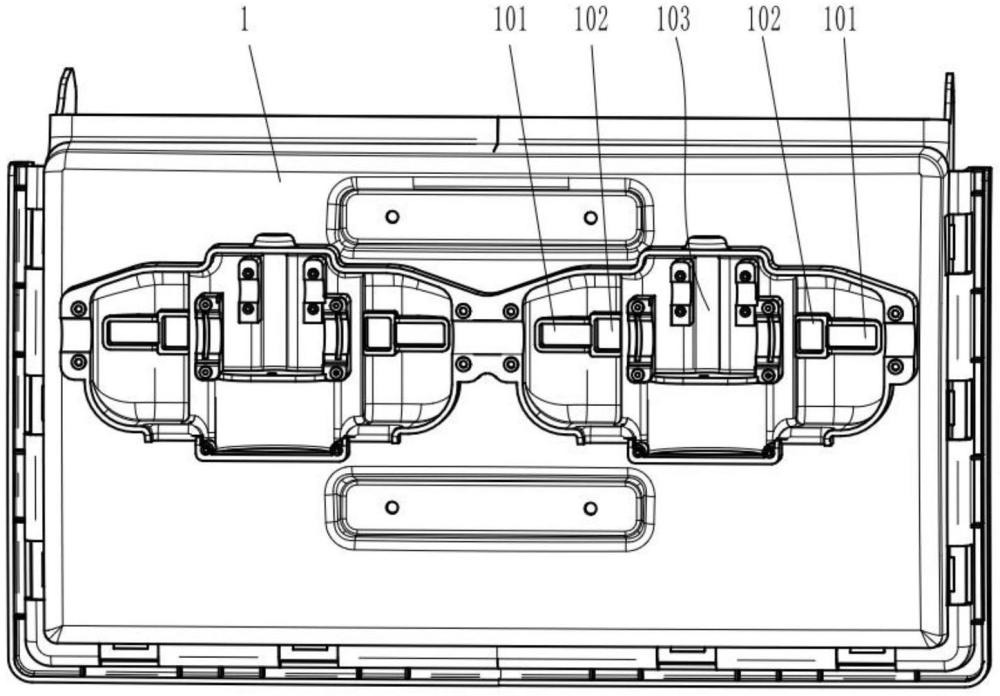
Referring to FIG. 2, FIG. 3 and FIG. 4, in the present embodiment, the two ends of the rotating shaft 2 are respectively provided with a first eccentric shaft sleeve 201 fixed relative to the rotation shaft 2, and the first eccentric shaft sleeve 201a is provided with an eccentric shaft segment 201a arranged at a set angle with the axis of the rotation shaft 2 (that is, the axis of the eccentric shaft segment 201a and the axis of the rotation shaft 2 are inclined to the axis of the rotation shaft 2, and the angle is generally set to be 5-20 degrees), and the first massage arm 4 sets are arranged on the eccentric shaft segment 201a of the first eccentric shaft sleeve 201a of the corresponding side , the leg support plate 1 is provided with a first limiting groove 101 arranged along its own length direction, and the first massage arm 4 is provided with a first limiting column 401 that is sliding and matched with the first limiting groove 101; It is understandable that the first massage arm 4 here is the movable sleeve is arranged on the eccentric shaft segment 201a of the first eccentric shaft sleeve 201 on the corresponding side, and when the rotating shaft 2 rotates, driven by the first eccentric shaft sleeve 201, the first limit groove 101 and the first limit column 401 can realize the reciprocating swing motion of the first massage arm 4. The first limiting groove 101 is arranged along the length of the leg support plate 1, which is also the lateral direction of the body, so as to realize the reciprocating swing of the first massage arm 4 in the direction of the width of the body; The motion control of the first massage arm 4 is realized through the eccentric sleeve structure, the structure is simple, the layout is convenient, and it is conducive to saving layout space; Of course, it is understandable that the first limit slot 101 is set corresponding to the first massage arm 4; More specifically, the two ends of the rotating shaft 2 are respectively fixed with an eccentric stop 203, the first eccentric shaft sleeve 201 and the eccentric stop 203 of the corresponding side are fixed by screws, and the eccentric stop 203 and the first eccentric shaft sleeve 201 are combined to form an axial limit for the first massage arm 4. More specifically, the first limit groove 101 here is a rectangular groove, and the length direction of the rectangular groove is consistent horizontally with the body.
Referring to FIG. 2, FIG. 3 and FIG. 4, in the present embodiment, the two ends of the rotating shaft 2 are respectively provided with a second eccentric shaft sleeve 202 fixed relative to the rotation shaft 2, the second eccentric shaft sleeve 202 is located on the inside of the first eccentric shaft sleeve 201 of the corresponding side (that is, the side of the center of the rotating shaft 2), the second massage arm 5 sets are arranged on the second eccentric shaft sleeve 202 of the corresponding side, and the leg support plate 1 is provided with a second limit groove 102 arranged along the direction of its own width. the second massage arm 5 is provided with a second limiting column 501 sliding to the second limiting groove 102; It is understandable that the second massage arm 5 movable sleeve is arranged on the second eccentric shaft sleeve 202, and when the rotating shaft 2 rotates, under the push of the second eccentric shaft sleeve 202, the second limit groove 102 and the second limit column 501 can be set together to realize the reciprocating swing of the second massage arm 5 in the direction of the length of the body; The motion control of the second massage arm 5 is realized through the eccentric sleeve structure, which is simple in structure and convenient in layout, which is conducive to saving layout space; Of course, it is understandable that the second limit slot 102 is set corresponding to the second massage arm 5; More specifically, the second eccentric shaft sleeve 202 is fixed connected with the first eccentric shaft sleeve 201 by bolts, and the second eccentric shaft sleeve 202 and the first eccentric shaft sleeve 201 are combined to form an axial limit to the second massage arm 5; More specifically, the second limit slot 102 here is a rectangular slot.
In the present embodiment, the first massage arm 4 of the two is arranged opposite to each other, and the top of the first massage arm 4 is flared outward, refer to FIG. 1, the two first massage arms 4 are arranged in an inverted eight-figure shape, which has a good compact structure, has a good massage effect on the legs, and is conducive to the insertion of the legs.
In the present embodiment, the first massage arm 4 is provided with a massage pad 402 with a heating function on the working surface; Specifically, the massage cushion 402 here is a silicone massage head, and an electric heating wire is set in the silicone massage head to achieve the heating function; By setting up the massage pad 402 with heating function, it is conducive to further improving the comfort of the massage.
In the present embodiment, the second massage arm 5 is arranged opposite to each other, and the second massage arm 5 is in an L-shaped structure; The structure is set up and arranged well, the massage effect on the legs is good, and the structure strength of the second massage arm 5 is good.
In the present embodiment, the top of the second massage arm 5 is inherently provided with a massage head 502, specifically, the massage head 502 adopts a silicone massage head, and the massage head 502 is conducive to further improving the massage effect by setting the massage head 502.
In the present embodiment, the leg support plate 1 is provided with a recessed part 103 with a recessed portion, and the driving mechanism 3 comprises a drive motor 301 and a transmission assembly 302 arranged in the recessed portion 103; The transmission assembly 302 comprises a worm 302a fixed as one with the output shaft of the drive motor 301, a first gear 302b meshed with the worm 302a, a second gear 302c fixed as one with the first gear 302b, and a third gear 302d fixed on the rotating shaft 2 and meshed with the second gear 302c; The drive mechanism 3 has a good compact layout, which is conducive to reducing the occupation of the upper space of the upper surface of the leg support plate 1. At the same time, the worm 302A and the first gear 302B form a first-stage reduction and torque increase structure, and the second gear 302C and the third gear 302D form a two-stage reduction and torque increase structure structure, which is conducive to the miniaturization design of the drive motor 301.
In the present embodiment, the upper cover of the recessed portion 103 is comprised with an upper cover plate 6, and the upper cover plate 6 covers the drive motor 301 and the transmission assembly 302 in the recessed portion 103; Specifically, here the upper cover plate 6 and the leg support plate 1 are fixed by bolts; By setting up the upper cover plate 6, it is conducive to reducing the operating noise of the drive motor 301 and the transmission assembly 302 and improving the comfort of use.
In the present embodiment, a face cover 7 is also included arranged on the leg support plate 1, and the face cover 7 wraps two sets of massage mechanisms, and a filling layer 8 is provided between the face cover 7 and the leg support plate 1; Specifically, the filling layer 8 is the foam layer, and the opening of the massage arm of the massage mechanism is preset on the foam layer; By setting the face cover7, it is conducive to ensuring the overall aesthetics.
Finally, it is stated that the above embodiments are only used to illustrate the technical solution of the present invention and not to limit it, although the present utility model is described in detail with reference to the better embodiments, ordinary personnel skilled in the field should understand that the technical scheme of the present utility model can be modified or equivalent to replace, without deviating from the purpose and scope of the technical solution of the present utility model, and it should be covered within the scope of the claims of the present model.










 400-4929-0909
 contact@catarc.com.cn