Invention content
An embodiment of the present application provides a rod point cloud data processing method, apparatus, electronic equipment and storage medium, the technical solution of the present application is as follows:
On the one hand, embodiments of the present application provide a rod point cloud data processing method, comprising:
Acquire the initial point cloud of rods; The rod includes the rod part;
Determine the initial rod point cloud corresponding to the rod from the initial point cloud;
The initial rod point cloud was fitted to a straight line, and the fitted straight line characterizing the rod was obtained.
Based on the direction information and vertical direction information of the fitted line, the initial point cloud is vertically corrected to obtain the middle point cloud of the rod.
The middle point cloud is compressed in the vertical direction to obtain a two-dimensional point cloud located in the same plane.
Determine the number of adjacencies within the first preset distance of each 2D point in the 2D point cloud;
Based on the number of adjacencies within the first preset distance of each 2D point, the target rod point cloud corresponding to the rod is determined from the 2D point cloud.
In some possible embodiments, the initial rod point cloud corresponding to the rod is determined from the initial point cloud, comprising:
The initial point cloud is processed horizontally to obtain a set of multiple first plane contour points corresponding to multiple first horizontal facets.
Circle fitting is performed on each set of first plane contour points in multiple sets of first plane contour points, and the center point of each first plane profile point set is determined.
Based on the center points of each first plane contour point set, the sequence of first circle center points is obtained.
Use the first circle point sequence as the initial rod point cloud corresponding to the rod.
In some possible embodiments, based on the center point of each first plane contour point set, after obtaining the first circle center point sequence, comprises:
Determine the distance between each center point in the first sequence of center points and adjacent center points;
For each center point, if the difference between the distance between the center point and the adjacent center point and the second preset distance is greater than or equal to the preset value, the center point is deleted to obtain the first center point sequence after filtering;
wherein the second preset distance is the distance between two adjacent first horizontal slices in a plurality of first horizontal slices; The preset value is determined according to the tilt angle threshold of the rod and the second preset distance.
In some possible embodiments, based on the orientation information and vertical direction information of the fitted line, the initial point cloud is vertically corrected to obtain an intermediate point cloud of the rod, comprising:
Determine the rotation matrix according to the direction information and vertical direction information of the fitted line;
The initial point cloud is rotated according to the rotation matrix to obtain the intermediate point cloud of the rod.
In some possible embodiments, the intermediate point cloud comprises a plurality of intermediate points and a plurality of intermediate points in each intermediate point three-dimensional coordinate value;
The middle point cloud is compressed vertically to obtain a two-dimensional point cloud located in the same plane, including:
Obtain the target vertical coordinate value of the target plane;
The vertical coordinate value of each intermediate point in the vertical direction is replaced with the vertical coordinate value of the target to obtain the projection point of each intermediate point on the target plane.
Based on the projection point of each intermediate point on the target plane, a two-dimensional point cloud is obtained.
In some possible embodiments, determining the number of adjacency points within the first preset distance of each two-dimensional point in a two-dimensional point cloud, comprising:
With each two-dimensional point as the center of the circle and the first preset distance as the radius, the search area of each two-dimensional point is determined;
The two-dimensional point located in the search area of each two-dimensional point is used as the adjacency point of each two-dimensional point, and the number of adjacent points corresponding to each two-dimensional point is obtained.
The first preset distance is determined based on the reference radius of the rod.
In some possible embodiments, based on the number of adjacencies within the first preset distance of each two-dimensional point, the target rod point cloud corresponding to the rod part is determined from the two-dimensional point cloud, comprising:
The number of adjacent points in the first preset distance of each two-dimensional point is statistically analyzed to determine the segmentation threshold;
The target rod point cloud is obtained by taking the number of adjacent points greater than or equal to the two-dimensional points corresponding to the segmentation threshold as the target points corresponding to the rods.
In some possible embodiments, further comprises:
Based on the fitted straight line, the position calibration of at least one target point in the target rod point cloud is carried out to obtain the calibrated target point.
Use the calibrated target point as the vector node for the rod.
In some possible embodiments, the rod further comprises at least one extension, and the method further comprises:
From the two-dimensional point cloud, at least one extension corresponding to the extension point cloud is obtained;
The extension point cloud was clustered to obtain the clustering results.
Based on the cluster processing results, the target point cloud block was determined from the extended point cloud.
The extension corresponding to the target point cloud block is used as the target extension.
The target point cloud blocks are filtered to obtain the vector nodes of the target extension.
In some possible embodiments, the target point cloud block is screened to obtain a vector node of the target extension, comprising:
Based on the target point cloud block and the fitted straight line, the extension direction information of the target extension corresponding to the target point cloud block is determined.
According to the extension direction information and vertical direction information, the target point cloud block is rotated to obtain the target point cloud after rotation processing.
The target point cloud after rotation treatment is processed horizontally, and a set of multiple second plane contour points corresponding to multiple second horizontal sections is obtained.
The circle fitting process is performed on each set of second plane contour points in multiple sets of second plane contour points, and the center point of each second plane profile point set is obtained.
Based on the center points of each second plane contour point set, the second center point sequence is obtained;
The second center point sequence is counter-rotated to obtain the second center point sequence after counterrotation treatment.
Use the sequence of second center points after anti-rotation processing as the vector node of the target extension.
On the other hand, embodiments of the present application also provide a rod-like point cloud data processing device, comprising:
Acquisition module for acquiring the initial point cloud of rods; The rod includes the rod part;
The first determination module is used to determine the initial rod point cloud corresponding to the rod from the initial point cloud;
The fitting module is used to fit the initial rod point cloud in a straight line to obtain the fitted straight line characterizing the rod;
The calibration module is used to perform vertical correction of the initial point cloud based on the direction information and vertical direction information of the fitted line, and obtain the intermediate point cloud of the rod;
The processing module is used to compress the intermediate point cloud in the vertical direction to obtain a two-dimensional point cloud located in the same plane;
The second determination module is used to determine the number of adjacencency points within the first preset distance of each two-dimensional point in the two-dimensional point cloud;
The third determination module is used to determine the target rod point cloud corresponding to the rod from the two-dimensional point cloud based on the number of adjacent points within the first preset distance of each two-dimensional point.
On the other hand, embodiments of the present application also provide an electronic device, the electronic device comprises a processor and a memory, the memory stores at least one instruction or at least one segment of a program, at least one instruction or at least one paragraph of program is loaded by the processor and executes the rod point cloud data processing method of the embodiment of the present application.
On the other hand, embodiments of the present application also provide a computer storage medium in which at least one instruction or at least one segment of program is stored, at least one instruction or at least one segment of program is loaded and executed by the processor to implement the rod point cloud data processing method of the embodiment of the present application.
The rod point cloud data processing method, apparatus, electronic equipment and storage medium provided by an embodiment of the present application have the following beneficial effects:
By acquiring the initial point cloud of the rod; The rod includes the rod part; Determine the initial rod point cloud corresponding to the rod from the initial point cloud; The initial rod point cloud was fitted to a straight line, and the fitted straight line characterizing the rod was obtained. Based on the direction information and vertical direction information of the fitted line, the initial point cloud is vertically corrected to obtain the middle point cloud of the rod. The middle point cloud is compressed in the vertical direction to obtain a two-dimensional point cloud located in the same plane. Determine the number of adjacencies within the first preset distance of each 2D point in the 2D point cloud; Based on the number of adjacencies within the first preset distance of each 2D point, the target rod point cloud corresponding to the rod is determined from the 2D point cloud. In this way, by vertical correction of the initial point cloud of the rod, the influence of rod tilt on the vectorization of the rod can be solved, and the vertical compression method combined with the characteristics of the vertical rod point cloud in the number of adjacent points can realize the rapid extraction of the target rod point cloud in the initial point cloud of the rod with high accuracy.
Specific embodiment
The following will be combined with the accompanying drawings in the embodiment of the present application, the technical solution in the embodiment of the present application is clearly and completely described, obviously, the described embodiment is only a part of the embodiment of the present application, not all embodiments. Based on the embodiments in the present application, all other embodiments obtained by those of ordinary skill in the art without performing creative labor fall within the scope of protection of the present application.
It should be noted that the terms "first", "second", etc. in the description and claims of the present application and the above drawings are used to distinguish similar objects, and do not have to be used to describe a specific order or sequence. It should be understood that the data so used may be interchangeable in appropriate cases so that the embodiments of the present application described herein may be implemented in an order other than those illustrated or described herein. Further, the terms "including" and "having" and any variation thereof are intended to cover non-exclusive inclusions, for example, a process, method, system, product or service apparatus comprising a series of steps or units need not be limited to those steps or units expressly listed, but may include other steps or units not expressly listed or inherent to those processes, methods, products or equipment.
Referring to FIG. 1, FIG. 1 is a schematic diagram of an application environment provided by an embodiment of the present application, as shown in FIG. 1, including a server 01 and a terminal device 02. Optionally, server 01 and terminal device 02 can be connected via a wireless link or via a wired link.
In some possible embodiments, the terminal device 02 performs point cloud data acquisition on the rod, and sends the initial point cloud collected to the server 01; Server 01 obtains the initial point cloud of the rod, processes the initial point cloud, and separates the vertical rod of the rod from the initial point cloud, that is, the target rod point cloud corresponding to the rod.
Specifically, server 01 can be an independent physical server, or a server cluster or distributed system composed of multiple physical servers, or a cloud server that provides cloud services, cloud databases, cloud computing, cloud functions, cloud storage, network services, cloud communications, middleware services, domain name services, security services, CDN (Content Delivery Network), and big data and artificial intelligence platforms and other basic cloud computing services. Optionally, the operating system running on the server 01 may include but is not limited to IOS, Linux, Windows, Unix, Android systems, etc.
In an optional embodiment, the terminal device 02 is configured with a lidar, the point cloud data of the rod is obtained by the lidar, and the point cloud data of the rod is preprocessed to obtain the initial point cloud of the rod.
It should be understood that the application environment shown in FIG. 1 is only an example, in practical applications, the terminal equipment or server may independently implement the rod point cloud data processing method of the embodiment of the present application, or the terminal device and server may cooperate to implement the rod point cloud data processing method of the embodiment of the present application, and the embodiment of the present application does not limit the specific application environment.
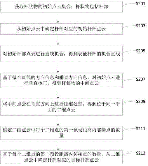
FIG 2 is a flowchart of a rod point cloud data processing method provided by an embodiment of the present application, as shown in FIG. 2, the rod point cloud data processing method can be applied to the server, comprising the following steps:
In Step S201, acquire the initial point cloud of the rod; The rod includes the rod part.
In an embodiment of the present application, the server may preprocess the original road environment point cloud data collected by the acquisition equipment, that is, the part of interest of the rod is divided from the original road environment point cloud data to obtain the initial point cloud, and the three-dimensional coordinate value of each initial point cloud in the initial point cloud; Alternatively, the server can directly acquire the initial point cloud of the rod from the acquisition device, which is configured to mainly collect the point cloud data of the rod, and the acquisition device directly sends the initial point cloud of the denoised rod and the 3D coordinate value of each initial point cloud to the server after removing noise. Among them, the three-dimensional coordinate value includes the vertical coordinate value (that is, the z-coordinate value), the first horizontal coordinate value (that is, the x-axis coordinate value), and the second horizontal coordinate value (that is, the y-axis coordinate value).
After the server obtains the initial point cloud of the rod, the subsequent steps of the initial point cloud are processed, and the process of processing can also be regarded as the process of vectorization, vectorization refers to the selection of vector nodes that can characterize each part of the rod from the initial point cloud of the rod, wherein the vector nodes of each part can build vector graphics representing each part, the vector graphics of each part can be combined to form a vector graphic representing the rod as a whole, and the vector graphics of the rod as a whole can be used for high-precision maps. And in the field of autonomous driving.
Typically, the rod includes a rod part, and in some possible embodiments, the rod further comprises at least one extension; Specifically, when the rod includes only one rod and no extension, the rod can be a traffic sign; When the rod includes a rod part and an extension, the rod can be a traffic light, a single-arm street light, etc.; When the rod includes a rod part and two extensions, the rod can be a high and low arm street light.
In related technologies, when processing the point cloud data of rods to obtain vector nodes, the problem of tilting rods in the actual road environment is not considered, and the vertical rod part and non-vertical extension of rods cannot be distinguished, resulting in inaccurate vector nodes in the final extraction, which in turn affects the accuracy of high-precision maps.
Based on this, an embodiment of the present application provides a rod point cloud data processing method, which can solve the interference problem of rod tilt, accurately extract the rod point cloud corresponding to the vertical rod from the initial point cloud of the rod, and further improve the accuracy of the vector node of the final extracted rod, and improve the accuracy and reliability of the high-precision map.
In step S203, the initial rod point cloud corresponding to the rod is determined from the initial point cloud.
In an embodiment of the present application, the server solves the tilt interference problem of the rod by making a vertical correction to the initial point cloud. Specifically, the server determines the initial rod point cloud corresponding to the vertical rod from the initial point cloud, then determines the fitted straight line of the vertical rod, and then uses the point cloud rotation method to straighten the rod as a whole.
In some possible embodiments, the initial rod point cloud corresponding to the rod corresponding to the determination from the initial point cloud may include the following steps as shown in FIG. 3:
In step S301, the initial point cloud is processed horizontally to obtain a plurality of first plane contour point sets corresponding to a plurality of first horizontal slices.
In this step, the initial point cloud is processed horizontally to obtain a set of first plane contour points corresponding to each first horizontal cut in multiple first horizontal slices. where the z-coordinate value is the same for each profile point in the first plane profile point set.
Optionally, the distance between two adjacent first horizontal slices in multiple first horizontal slices is the second preset distance.
Specifically, a set of horizontal slices is obtained at a certain spacing d, and the horizontal slice equation is shown in Equation (1):
z=h...... (1)
Among them, d represents the second preset distance, which can be set according to the actual height of the rod; The z-values of different points on the same horizontal section are the same, all are h; Different horizontal slices have different z-values, and the h-values range from 0 to the maximum height of the rod, H.
Use the above horizontal tangent surface to perform horizontal sectioning of the initial point cloud of the rod, optionally, the slice thickness is d/2, obtain the contour points of the rod point cloud on the horizontal plane of each spacing, and each horizontal cut surface corresponds to a set of contour points; In this process, the z-coordinate value of each set of planar contour points is uniformly assigned to the z-coordinate value h of the horizontal section.
As shown in FIG. 4, FIG. 4 is a schematic diagram of a horizontal section effect provided by an embodiment of the present application; The initial point cloud of the single-arm street lamp shown on the left side in Figure 4 is horizontally sliced, and the horizontal section contour points corresponding to different heights obtained are shown on the right side in Figure 4.
In Step S303, each first plane profile point set in a plurality of first plane profile point sets is circle-fitted, determining the center point of each first plane profile point set.
In step S305, based on the central point of each first planar contour point set, the first central point sequence is obtained.
In the above step, each first plane profile point set is circle-fitted, and the center point of each first plane profile point set is obtained, forming a sequence of first circle center points. Subsequently, the first circle center point sequence is used to fit the straight line, and the straight line that can run through the vertical rod point cloud is obtained.
Specifically, as shown in Figure 4, the obtained groups of contour points are circle-fitted respectively, and the central coordinates of each group of contour points are obtained to form a circle center sequence point.
In step S307, the first circle center point sequence is used as the initial rod point cloud corresponding to the rod.
Before straight line fitting, in order to exclude the influence of non-vertical rod points, the first center point sequence after screening is obtained by screening the rod point cloud of the first circle center point sequence, and the separation points in the first center point sequence are removed.
In some possible embodiments, the rod point cloud screening of the first circle point sequence described above, the first center point sequence after screening, may include the following steps as shown in FIG. 5:
In Step S501, determine the distance between each central point and adjacent central points in the first circle point sequence.
In step S503, for each center point, if the difference between the distance between the center point and the adjacent center point and the second preset distance is greater than or equal to the preset value, the center point is deleted to obtain the first center point sequence after filtering.
Specifically, calculate the Euclidean distance d' between each center point and the adjacent center point in the first circle point sequence, and then compare it with the horizontal slice spacing d, that is, the second preset distance, to determine the deviation value between the two ∆ d.
Consider that if the center point is fitted by a point cloud slice containing a non-vertical rod, then the straight-line distance d' between it and the adjacent center point must be much greater than the horizontal slice spacing d. Therefore, a preset value is set ε, and if the ∆ is ≥ε, the corresponding center point is filtered. Among them, the preset value can be determined according to the tilt angle threshold of the rod ε the second preset distance; Specifically, it can be determined by referring to the following formula (2):
ε=(secθ-1)×d...... (2)
where θ represents the tilt angle threshold of the vertical rod, that is, the maximum tilt angle; secθ represents the secant of the maximum tilt angle; d represents the second preset distance, which is the distance between two adjacent first horizontal slices in multiple first horizontal slices.
In the above embodiment, by removing the dissociative point in the first circle point sequence and excluding the influence of non-vertical rod points, it can be ensured that the first circle sequence points after screening belong to the vertical rod part, and the subsequent fitted straight line can accurately penetrate the rod point cloud.
In Step S205, the initial rod point cloud is fitted to a straight line to obtain a fitted straight line characterizing the rod.
In the embodiment of the present application, the initial rod point cloud is fitted in a straight line, and the direction information of the fitted straight line and the fitted straight line characterizing the rod is obtained, and the direction information can refer to the direction vector of the fitted line.
Specifically, using the screened initial rod point cloud, the fitted straight line L 1 running through the vertical rod is fitted, and the fitted straight line L1 equation can be expressed as follows equation (3):
(x-b1)/a1 =(x-b2)/a2 =(x-b3)/a3...... (3)
where (a 1,a2,a 3) is the direction vector of the line L1 and (b1,b2,b3) is the intercept vector.
In step S207, based on the direction information and vertical direction information of the fitted line, the initial point cloud is vertically corrected to obtain the middle point cloud of the rod.
In an embodiment of the present application, the server performs a vertical correction of the initial point cloud, specifically, based on the fitted straight line L 1 of the vertical rod, the initial point cloud of the rod is rotated so that the fitted line L1 of the rotated rod point cloud can be parallel to the vertical direction (i.e., the z-axis).
In some possible embodiments, the initial point cloud is vertically corrected based on the orientation information and vertical direction information of the fitted line, and the intermediate point cloud of the rod is obtained, which may include the following steps as shown in FIG. 6:
In step S601, the rotation matrix is determined based on the orientation information and vertical direction information of the fitted line.
In this step, the rotation matrix R 1 is calculated using the direction vector (a 1,a2,a3) of the line L 1 and the direction vector of the z axis (0,0,1).
Specifically, the rotation matrix can be calculated using the Rodrigue rotation formula, let v be the vector product of the linear L 1 direction vector (a 1,a 2, a3) and the z-axis direction vector, s is the norm of v, c is the inner product of the two vectors, then R1 is calculated as shown in (4) below:
![]()
where I represents the identity matrix; [v]× represents the antisymmetric fork-multiplication matrix of v, in combination with equation (4) v = (a2,-a1,0), [v]× expression as shown in equation (5) below:
![]()
In step S603, the initial point cloud is rotated according to the rotation matrix to obtain the intermediate point cloud of the rod.
Specifically, the rotation matrix R1 is used to rotate the initial point cloud of the rod to obtain the righted rod point cloud, that is, the intermediate point cloud. The point cloud rotation method is shown in the following equation (6):
![]()
where the![]() three-dimensional coordinate value of the initial point cloud is described;
three-dimensional coordinate value of the initial point cloud is described; ![]() Represents the three-dimensional coordinates of the rotated intermediate point cloud Value.
Represents the three-dimensional coordinates of the rotated intermediate point cloud Value.
In the above embodiment, by rotating the initial point cloud of the rod, the rotated rod point cloud is parallel to the Z-axis direction to facilitate the processing of subsequent steps.
In step S209, the intermediate point cloud is compressed in the vertical direction to obtain a two-dimensional point cloud located in the same plane.
In an embodiment of the present application, the middle point cloud of the straightened rod includes a plurality of intermediate points and a plurality of intermediate points in the three-dimensional coordinate value of each intermediate point. The server uses the z-axis compression method to compress the intermediate point cloud in the z-axis direction to obtain a two-dimensional point cloud located in the same xy plane.
In some possible embodiments, the intermediate point cloud is compressed vertically to obtain a two-dimensional point cloud located in the same plane, which may include the following steps as shown in FIG. 7:
In Step S701, obtain the target vertical coordinate value of the target plane.
Here, the target plane selects the xy plane with a z-axis coordinate value of 0, and correspondingly, the target vertical coordinate value is 0.
In step S703, the vertical coordinate value of each intermediate point in the vertical direction is replaced with the target vertical coordinate value, and the projection point of each intermediate point on the target plane is obtained.
In Step S705, a two-dimensional point cloud is obtained based on the projection point of each intermediate point on the target plane.
Specifically, the Z-axis coordinate value in the three-dimensional coordinate value of each intermediate point is removed, and only the x-axis coordinate value and y-axis coordinate value of each intermediate point are retained, and the projection point of each intermediate point on the target plane XOY is obtained. Then, based on the projection point of each intermediate point on the target plane XOY, a two-dimensional point cloud is obtained.
In the above embodiment, the middle point cloud after righting is projected onto the XOY plane to facilitate the subsequent further division of the vertical rod part and the non-vertical extension part of the point cloud in the two-dimensional plane.
In step S211, determine the number of adjacencies within the first preset distance of each two-dimensional point in the two-dimensional point cloud.
In step S213, based on the number of adjacencies within the first preset distance of each two-dimensional point, the target rod point cloud corresponding to the rod part is determined from the two-dimensional point cloud.
In the embodiment of the present application, considering that the point cloud of the vertical rod in the rod has elongation on the z-axis, after compression in the z-axis, the density of the point cloud of the rod part will be very high, and the non-vertical extension part is the opposite, therefore, this feature can be used to extract the point cloud of the vertical rod part, and distinguish the vertical rod part from the non-vertical rod body.
In the embodiment of the present application, the density is quantified by the number of adjacent points within the first preset distance of the two-dimensional point. Thus, the server can determine the number of neighbors within the first preset distance of each two-dimensional point in the two-dimensional point cloud through the method of neighbor search. Then, based on the number of adjacencies within the first preset distance of each 2D point, the target rod point cloud corresponding to the rod is determined from the 2D point cloud. After determining the target pole point cloud, the server can directly use the part of the 2D point cloud except the target pole point cloud as a non-vertical extension point cloud.
In some possible embodiments, the number of adjacency points within the first preset distance of each two-dimensional point in the two-dimensional point cloud may include the following steps as shown in FIG. 8:
In step S801, the search area of each two-dimensional point is determined with each two-dimensional point as the center of the circle and the first preset distance as the radius.
The first preset distance is determined based on the reference radius of the rod.
In step S803, the two-dimensional point located in the search area of each two-dimensional point is used as the adjacency point of each two-dimensional point, and the number of adjacencency points corresponding to each two-dimensional point is obtained.
Specifically, the two-dimensional points that fall into the search area of each two-dimensional point will be used as the adjacency points of the two-dimensional point, and then the number of critical points in the search area of each two-dimensional point will be counted.
In some possible embodiments, based on the number of adjacencies within the first preset distance of each two-dimensional point, the target rod point cloud corresponding to the rod part is determined from the two-dimensional point cloud, which may include the following steps as shown in FIG. 9:
In Step S901, the number of adjacent points within the first preset distance of each two-dimensional point is statistically analyzed to determine the segmentation threshold.
In step S903, the number of adjacent points is greater than or equal to the two-dimensional point corresponding to the segmentation threshold, as the target point corresponding to the rod, and the target rod point cloud is obtained.
Specifically, using the difference between the point cloud of the vertical rod part in the plane and the point cloud of the non-vertical extension part in the characteristics of the number of two-dimensional adjacency points, the point cloud of the vertical rod part is extracted, firstly, the number of adjacency points corresponding to each two-dimensional point is statistically analyzed, please refer to FIG. 10, FIG. 10 is a statistical histogram of adjacency points provided by the embodiment of the present application, wherein the horizontal axis represents the serial number of each two-dimensional point, and the vertical axis represents the number of adjacent points corresponding to each two-dimensional point; Based on the statistical histogram, the number of adjacent points corresponding to each two-dimensional point is statistically analyzed, and the natural fracture method is used to determine the segmentation threshold T of the vertical rod part and the non-vertical extension part on the number of adjacent points.
Since the number of adjacencies of the two-dimensional points corresponding to the vertical rod is significantly greater than the number of adjacencies of the two-dimensional points corresponding to the non-vertical extension, the number of adjacencies greater than or equal to the two-dimensional points of the segmentation threshold T can be determined as the target points corresponding to the rod to obtain the target rod point cloud.
In some possible embodiments, the method of embodiments of the present application may further include the following steps as shown in FIG. 11:
In step S1101, based on the fitted straight line, the position calibration of at least one target point in the target rod point cloud is obtained.
In Step S1103, the calibrated target point is used as the vector node of the rod part.
In the above steps, the server can select the target point with the largest z-coordinate value and the target point with the smallest z-coordinate value in the target rod point cloud, that is, the points at both ends of the rod, and after calibrating the position of these two target points, the vector nodes of the rod can be obtained.
Specifically, the maximum value of z-axis coordinates zmax and the minimum z-axis coordinate zmin in the target rod point cloud are selected and substituted into the straight-line equation fitting the straight line L 1, respectively, and the points corresponding to these two maximum values on the line L1 are calculated as the upper and lower endpoint coordinates of the vertical rod in the rod, as shown in Equation (7) below:
![]()
where (x 1,y 1,z1) and (x 2,y 2,z2) represent the three-dimensional coordinate values of the vector nodes of the rod; zmax and zmin are the maximum and minimum values of the target rod point cloud in the z-axis direction. a 1, a2, b 1, b2 are the straight-line equation parameters of the line L1.
In an embodiment of the present application, after dividing the target rod point cloud or determining the vector node of the rod in the rod, the server may extract the non-vertically extended point cloud and vectorize the non-vertical extension portion of the remaining point cloud in the two-dimensional point cloud.
Considering that the rod may have multiple extensions, the remaining point clouds are not all point clouds of the same extension, such as high and low arm street lights have two extensions.
Further, in some possible embodiments, the rod further comprises at least one extension, and the method of embodiments of the present application may further include the following steps as shown in FIG. 12:
In step S1201, from the two-dimensional point cloud, at least one extension corresponding to the extension point cloud is obtained.
In step S1203, the extension point cloud is clustered to obtain the clustering result.
In the above steps, the server deletes the target pole point cloud from the two-dimensional point cloud and obtains the remaining part of the point cloud, that is, the extension point cloud corresponding to the extension. Since considering the existence of more than two extensions of the rod, the server clustered the remaining extension point clouds, and the DBSCAN density clustering algorithm can be used to obtain the clustering processing results, which include at least one point cloud block, and when there are multiple point cloud blocks, each point cloud block indicates a different category of extensions.
In Step S1205, based on the cluster processing results, the target point cloud block is determined from the extension point cloud.
When the clustering results indicate the presence of a point cloud block, the point cloud is taken directly as the target point cloud block.
In step S1207, the extension corresponding to the target point cloud block is taken as the target extension.
In this step, when the clustering results indicate the presence of at least two point cloud blocks, it indicates the presence of at least two extensions of different categories. Therefore, it is necessary to select one point cloud block from at least two point cloud blocks as the target point cloud block, and the extension corresponding to the target point cloud block as the target extension part.
Specifically, the above selection of one point cloud block from at least two point cloud blocks as the target point cloud block may include the following steps: for each point cloud block, calculate its maximum distance D to the fitted line L1, and take the maximum distance D as the extension distance corresponding to the point cloud block; Then, compare the size of the extension distance of each extension, and select the point cloud block corresponding to the extension with the longest extension as the target point cloud block.
In practical applications, if the longest extension distance is less than or equal to 1m, the subsequent vectorization of the non-vertical extension can be carried out.
In step S1209, the target point cloud block is screened to obtain the vector node of the target extension.
In this step, the server filters the target point cloud block to obtain the vector node of the target extension and completes the vectorization of the non-vertical extension.
In some possible embodiments, the target point cloud block is screened to obtain a vector node of the target extension, which may include the following steps as shown in FIG. 13:
In step S1301, based on the target point cloud block and the fitted straight line, determine the extension direction information of the target extension corresponding to the target point cloud block.
where the extension direction information can refer to the extension direction vector. Specifically, the server first determines the point P1 farthest from the fitted line L1 in the target point cloud, and then determines that the point P1 is at the vertical pointP2 of the lineL1; ConnectingP2 andP1 yields the line L 2, and the direction vector of the line L2 is the extension direction vector of the target extension.
In step S1303, according to the extension direction information and vertical direction information, the target point cloud block is rotated to obtain the target point cloud block after rotation processing.
In this step, after determining the extension direction vector of the target extension, the server calculates the rotation matrix R 2 according to the direction vector (0,0,1) and the direction vector of the straight line L 2, and rotates the target point cloud according to the rotation matrix R2 to obtain the target point cloud after rotation processing, and the target point cloud after rotation is parallel to the z axis.
In step S1305, the target point cloud after rotation processing is horizontally sliced to obtain a plurality of second plane contour points corresponding to a plurality of second horizontal slices.
In step S1307, each second plane contour point set in a plurality of second plane contour point sets is circle-fitted to obtain the center point of each second plane profile point set.
In Step S1309, based on the central point of each second plane contour point set, a sequence of second central points is obtained.
Through the above steps S1305~S1309, the vector nodes of the target extension are filtered. Since the above sequence of second central points is processed based on the rotation of the target point cloud, it cannot be directly used as a vector node of the target extension, and anti-rotation processing is required.
In step S1311, the second central point sequence is counter-rotated to obtain the second central point sequence after counterrotation treatment.
In step S1313, the second sequence of central points after anti-rotation processing is used as the vector node of the target extension.
Specifically, calculate the inverse matrix![]() of the rotation matrixR2, using
of the rotation matrixR2, using![]() the inverse rotation of the second circle point sequence, The second center point sequence after the anti-rotation treatment is obtained, and the second center point sequence after the anti-rotation treatment can be directly used as the target The vector node of the extension.
the inverse rotation of the second circle point sequence, The second center point sequence after the anti-rotation treatment is obtained, and the second center point sequence after the anti-rotation treatment can be directly used as the target The vector node of the extension.
In the above embodiment, by rotating the target extension to be parallel to the z-axis to facilitate the horizontal section processing of the extension, and by circularing fitting the contour point set of each horizontal section, the vector node of the target extension is obtained, and the vectorization of the non-vertical extension is realized.
In summary, the embodiment of the present application solves the influence of rod tilt on rod vectorization by vertical correction of the initial point cloud of the rod, and by combining the characteristics of the vertical rod point cloud in the number of adjacent points, the rapid extraction of the target rod point cloud in the initial point cloud of the rod is realized with high accuracy; Further, the efficiency and accuracy of rod point cloud vectorization are improved.
An embodiment of the present application also provides a rod point cloud data processing device, FIG 14 is a schematic view of the structure of a rod point cloud data processing device provided by an embodiment of the present application, as shown in FIG. 14, the device comprises:
Acquisition module 1401 for acquiring the initial point cloud of rods; The rod includes the rod part;
The first determination module 1402 is used to determine the initial rod point cloud corresponding to the rod from the initial point cloud;
Fitting module 1403, for straight-line fitting of the initial rod point cloud, to obtain the fitted straight line characterizing the rod;
Calibration module 1404, for vertical correction of the initial point cloud based on the direction information and vertical direction information of the fitted line, and obtain the intermediate point cloud of the rod;
processing module 1405, for compressing the intermediate point cloud in the vertical direction to obtain a two-dimensional point cloud located in the same plane;
a second determination module 1406 for determining the number of adjacency points within the first preset distance of each two-dimensional point in a two-dimensional point cloud;
The third determination module 1407 is used to determine the target rod point cloud corresponding to the rod part from the two-dimensional point cloud based on the number of adjacent points within the first preset distance of each two-dimensional point.
In some possible embodiments, the first determination module 1402, is also used to perform horizontal facet processing on the initial point cloud, obtaining a plurality of first plane contour point sets corresponding to a plurality of first horizontal slices; Circle fitting is performed on each set of first plane contour points in multiple sets of first plane contour points, and the center point of each first plane profile point set is determined. Based on the center points of each first plane contour point set, the sequence of first circle center points is obtained. Use the first circle point sequence as the initial rod point cloud corresponding to the rod.
In some possible embodiments, the distance between two adjacent first horizontal sections in a plurality of first horizontal slices is a second preset distance;
The first determination module 1402, also used to determine the distance between each center point and adjacent center points in the first circle point sequence; For each center point, if the difference between the distance between the center point and the adjacent center point and the second preset distance is greater than or equal to the preset value, the center point is deleted to obtain the first center point sequence after filtering; wherein the second preset distance is the distance between two adjacent first horizontal slices in a plurality of first horizontal slices; The preset value is determined according to the tilt angle threshold of the rod and the second preset distance.
In some possible embodiments, the correction module 1404, is also used to determine the rotation matrix according to the orientation information and vertical direction information of the fitted line; The initial point cloud is rotated according to the rotation matrix to obtain the intermediate point cloud of the rod.
In some possible embodiments, the intermediate point cloud comprises a plurality of intermediate points and a plurality of intermediate points in each intermediate point three-dimensional coordinate value;
processing module 1405, also used to obtain the target vertical coordinate value of the target plane; The vertical coordinate value of each intermediate point in the vertical direction is replaced with the vertical coordinate value of the target to obtain the projection point of each intermediate point on the target plane. Based on the projection point of each intermediate point on the target plane, a two-dimensional point cloud is obtained.
In some possible embodiments, the second determination module 1406, is also used to determine the search area of each two-dimensional point with each two-dimensional point as the center of the circle and the first preset distance as the radius; The two-dimensional point located in the search area of each two-dimensional point is used as the adjacency point of each two-dimensional point, and the number of adjacent points corresponding to each two-dimensional point is obtained. The first preset distance is determined based on the reference radius of the rod.
In some possible embodiments, the third determination module 1407, is also used to perform a statistical analysis of the number of adjacent points within the first preset distance of each two-dimensional point, to determine the segmentation threshold; The target rod point cloud is obtained by taking the number of adjacent points greater than or equal to the two-dimensional points corresponding to the segmentation threshold as the target points corresponding to the rods.
In some possible embodiments, the apparatus further comprises a fourth determination module, the fourth determination module is used to calibrate the position of at least one target point in the target rod point cloud based on the fitted straight line, and the calibrated target point is obtained; Use the calibrated target point as the vector node for the rod.
In some possible embodiments, the rod further comprises at least one extension, and the device further comprises a fifth determining module,
The fifth determination module is used to obtain at least one extension corresponding to the extension point cloud from the two-dimensional point cloud; The extension point cloud was clustered to obtain the clustering results. Based on the cluster processing results, the target point cloud block was determined from the extended point cloud. The extension corresponding to the target point cloud block is used as the target extension. The target point cloud blocks are filtered to obtain the vector nodes of the target extension.
In some possible embodiments, the fifth determination module, also used to determine the extension direction information of the target extension corresponding to the target point cloud block based on the target point cloud block and the fitted straight line; According to the extension direction information and vertical direction information, the target point cloud block is rotated to obtain the target point cloud after rotation processing. The target point cloud after rotation treatment is processed horizontally, and a set of multiple second plane contour points corresponding to multiple second horizontal sections is obtained. The circle fitting process is performed on each set of second plane contour points in multiple sets of second plane contour points, and the center point of each second plane profile point set is obtained. Based on the center points of each second plane contour point set, the second center point sequence is obtained; The second center point sequence is counter-rotated to obtain the second center point sequence after counterrotation treatment. Use the sequence of second center points after anti-rotation processing as the vector node of the target extension.
The apparatus and method embodiments in the embodiments of the present application are based on the same application idea.
FIG 15 is a block diagram of an electronic device for rod point cloud data processing provided by embodiments of the present application, the electronic device may be a terminal, and its internal structure diagram may be shown in FIG. 15. The electronics include processors, memory, network interfaces, displays, and input devices connected via a system bus. Wherein the processor of the electronic device is used to provide computing and control capabilities. The memory of the electronic device includes a non-volatile storage medium, internal memory. This non-volatile storage medium stores an operating system and computer programs. This internal memory provides an environment for the operation of operating systems and computer programs in non-volatile storage media. The network interface of the electronic device is used to communicate with external terminals through network connections. The computer program is executed by the processor to implement a rod-like point cloud data processing method. The display screen of the electronic device may be an LCD screen or an electronic ink display, and the input device of the electronic device may be a touch layer covered on the display, or a button, trackball or trackpad set on the electronic device shell, and may also be an external keyboard, trackpad or mouse.
Those skilled in the art may understand that the structure shown in FIG. 15 is only a block diagram of a portion of the structure related to the present application proposal, and does not constitute a limitation of the electronic device to which the present application scheme is applied, the specific electronic device may include more or fewer components than shown in the FIG., or a combination of certain components, or have a different arrangement of components.
In an exemplary embodiment, an electronic device is also provided, comprising: a processor; memory for storing executable instructions of the processor; Wherein the processor is configured to execute the instruction to implement a rod point cloud data processing method such as in an embodiment of the present application.
In an exemplary embodiment, a computer-readable storage medium is also provided, when the instructions in the storage medium are executed by the processor of the electronic device, enabling the electronic device to perform the rod-like point cloud data processing method in the embodiment of the present application.
Those of ordinary skill in the art may understand that the process of implementing all or part of the method described above embodiments may be completed by a computer program instructing the relevant hardware, the computer program may be stored in a non-volatile computer-readable storage medium, the computer program may include a process of embodiments such as the above methods when executed. Wherein any reference to memory, storage, database or other media used in each embodiment provided in the present application may include non-volatile and / or volatile memory. Non-volatile memory may include read-only memory (ROM), programmable ROM (PROM), electrically programmable ROM (EPROM), electrically erasable programmable ROM (EEPROM), or flash memory. Volatile memory may include random access memory (RAM) or external cache memory. As a description rather than limitation, RAM is available in many forms, such as static RAM (SRAM), dynamic RAM (DRAM), synchronous DRAM (SDRAM), dual data rate SDRAM (DDRSDRAM), enhanced SDRAM (ESDRAM), synchronous link (Synchlink) DRAM (SLDRAM), memory bus (Rambus) direct RAM (RDRAM), direct memory bus dynamic RAM ( DRDRAM), and memory bus dynamic RAM (RDRAM).
Those skilled in the art will easily think of other embodiments of the present application after considering the description and practice of the invention disclosed herein. The present application is intended to cover any variant, use, or adaptable variation of the present application, which follows the general principles of the present application and includes common knowledge or common knowledge or common art means in the art not disclosed in the present application. The description and embodiments are considered exemplary only, and the true scope and spirit of the present application are indicated by the claims below.
It should be understood that the present application is not limited to the precise structure described above and shown in the drawings, and may be modified and altered without departing from its scope. The scope of this application is limited only by the attached claims.










 400-4929-0909
 contact@catarc.com.cn