Contents of the invention
The object of the present invention is to provide a vehicle working condition simulation system and application method that can accurately simulate tire working conditions.
The present invention provides a vehicle working condition simulation system, including a support device fixed connected to the wheel hub disc of the automobile to simulate the wheel and a control device connected to the support device to collect the height data of the support device, load data and change the height of the support device, the support device includes a base placed horizontally to measure the load of the support device, the bottom end is fixed laterally on the base can swing longitudinally along the base longitudinal fan expansion member, The base and the telescopic member are provided with an angle table indicating the angle between the base and the telescopic member;
The control device includes a programmable controller, the programmable controller comprises a tire load-tire radius correspondence, the programmable controller is used to collect the load data of the support device and substitute the tire load-tire radius correspondence to obtain the tire radius and change the height of the telescopic member with reference to the tire radius.
Further, the telescopic member includes a cylinder block connected to the base controlled by the control device to charge and deflate, a piston rod driven by the pressure in the cylinder body to move up and down with respect to the cylinder block, and a flange that fixes the piston rod with the wheel hub disc of the car.
Further, the telescopic member further comprises a height sensor for measuring the height of the support device and transmitting the height data to the control device, the height sensor includes a static slide fixed on the cylinder block and a moving slide fixed on the piston rod that can move with the piston rod and make sliding contact with the static sliding blade, and the moving slide and the static slide blade can send different electrical signals to the control device when the relative position is different.
Further, the cylinder block is connected to the base by a rotary pin, and the cylinder block can make a longitudinal fan-shaped swing around the central axis of the rotary pin.
Further, the angle table comprises a scale plate fixed on the base and a pointer fixed on the cylinder block that can swing with the cylinder block, the scale plate is marked with a scale, and the front end of the pointer points to the scale on the scale plate.
Further, the base is provided with a load cell connected to the programmable controller to measure the load data of the support device.
Further, the control device further comprises a pressurized pump connected to the programmable controller to pressurize the cylinder and a pressure relief valve for relieving pressure in the cylinder.
The present invention also provides an application method of a vehicle working condition simulation system, applied to the vehicle working condition simulation system as described above, including steps S1 to S3, the step S1 is to connect the automobile hub disc with the telescopic member, and the tire is simulated by a support device; The step S2 collects the load data and height data of the support device for the programmable controller, and substitutes the load data into the tire load-tire radius correspondence to obtain the corresponding tire radius and changes the height of the telescopic member with reference to the corresponding tire radius; The step S3 is to record the data of the angle table and the data of the car suspension.
Further, the step S2 includes steps S21 to S22, the step S21 collects the load data and height data of the support device for the programmable controller, and substitutes the load data into the tire load-tire radius correspondence to derive the corresponding tire radius; The step S22 compares the height data and the corresponding tire radius for the programmable controller, and changes the height of the telescopic member until the height data of the support device is equal to the corresponding tire radius.
Further, the control device further comprises a pressurized pump connected to the programmable controller to pressurize the cylinder and a pressure relief valve for relieving pressure in the cylinder; The step S22 compares the height data and the corresponding tire radius for the programmable controller, and pressurizes the cylinder body through the pressurized pump or changes the height of the telescopic member for the cylinder block relief valve until the height data of the support device is equal to the corresponding tire radius.
The vehicle working condition simulation system provided by the present invention simulates the replacement tire through the support device, and the suspension will not be covered in the measurement, and the suspension data can be directly measured without frequent tire disassembly; Through the programmable controller with built-in tire load-radius equation, the height of the support device can be adjusted directly according to the vehicle load to simulate the tire of the corresponding radius; The telescopic parts can swing longitudinally along the base, which is different from the traditional fixed tire bracket auxiliary detection, which is more in line with the actual working conditions; Real-time detection of tire inclination through the angle table makes chassis attitude measurement more convenient, intuitive and accurate.
Specific embodiment
The following in combination with the accompanying drawings and embodiments, the specific embodiments of the present invention are further described in detail. The following embodiments are used to illustrate the present invention, but are not intended to limit the scope of the present invention.
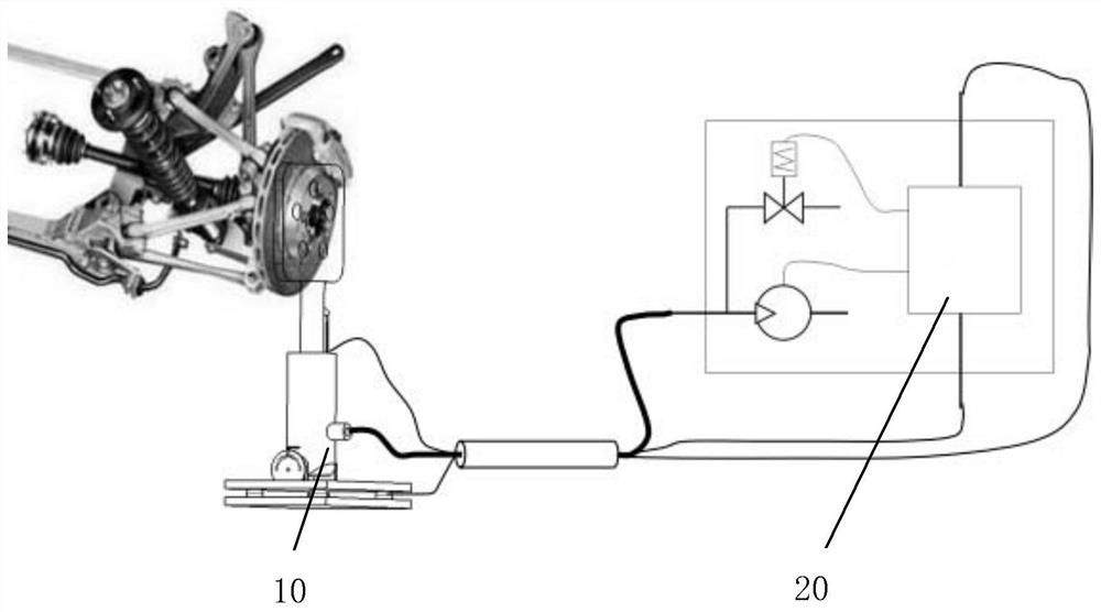
Referring to FIGS. 1 to FIG. 8, embodiments of the present invention provide a vehicle working condition simulation system for testing and verification of the vehicle chassis during the development and manufacturing of automobiles, including a support device 10 and a control device 20 connected to the support device 10. The support device 10 includes a base 11, a telescopic member 12, an angle table 13, a base 11 is placed horizontally and a load cell 111 is provided on the base 11 to measure the load of the support device 10. The telescopic member 12 is connected to the base 11 and can swing longitudinally along the base 11, and the angle table 13 is used to indicate the angle between the telescopic member 12 and the base 11.
Referring to FIGS. 2 to FIG. 5, the telescopic member 12 includes a cylinder block 121, a piston rod 122, a flange 123 and a height sensor 124, one end of the flange 123 is connected to the piston rod 122, and the other end is used to fix the connection with the automobile hub disc. One end of the piston rod 122 extends into the cylinder block 121, and the pressure in the cylinder block 121 can drive the piston rod 122 to move up and down with respect to the cylinder block 121. The cylinder block 121 is connected to the base 11 by a rotating pin 112 so that the cylinder block 121 can make a longitudinal fan oscillation around the central axis of the rotary pin 112 (as shown in FIG. 4). The angle table 13 includes a scale plate 131 and a pointer 132, the scale plate 131 is fixed on the base 11 and perpendicular to the upper surface of the base 11, the pointer 132 is fixed on the cylinder block 121 and can swing with the cylinder block 121 (as shown in FIG. 5). The scale 131 is used to indicate the angle of the scale, the front end of the pointer 132 points to the scale on the scale 131.
When the pointer 132 swings with the cylinder block 121, the pointer 132 points to different scales on the scale plate 131, and the indicated scale is the angle between the support device 10 and the horizontal plane. The support device 10 is fixed and connected to the wheel disc of the automobile to simulate the automobile tire, and the camber angle of the tire in the chassis test of the whole vehicle can be recorded by recording the scale of the angle table 13. In other embodiments, the angle table 13 may also be connected to the control device 20, the angle table 13 transmits the angle data to the control device 20 after the mode electric conversion, and the control device 20 may record and output tire camber angle data.
The vehicle working condition simulation system provided in this implementation, the telescopic member 12 can swing longitudinally along the base 11, which is different from the traditional fixed tire bracket auxiliary detection, and is more in line with the actual working conditions. The real-time detection of tire inclination angle through angle table 13 makes chassis attitude measurement more convenient, intuitive and accurate.
As shown in FIG. 6, the height sensor 124 includes a static slide 1241 and a moving slide 1242, the static slide 1241 is fixed on the cylinder block 121, the moving slide 1242 is fixed on the piston rod 122 and can move up and down with the piston rod 122, the front end of the moving slide 1242 and the sliding contact with the static slide 1241. The height sensor 124 is connected to the control device 20, and the relative position of the moving slide 1242 and the static slide 1241 is different, and different electrical signals can be sent to the control device 20. The height represented by different electrical signals is preset in the control device 20, and the height of the support device 10 can be measured by the height sensor 124, that is, the radius of the tire simulated by the support device 10.
The cylinder block 121 is provided with a connecting hole 1211, the connecting hole 1211 is connected to the control device 20, and the control device 20 can control the pressure in the cylinder block 121 through the connection hole 1211, so that the piston rod 122 can move up and down relative to the cylinder block 121. In the present embodiment, the telescopic member 12 is a telescopic cylinder, the piston rod 122 is driven by the air pressure in the cylinder block 121, in other embodiments, the telescopic member 12 may also be a hydraulic cylinder or other form of lifting mechanism.
As shown in FIG. 7, the control device 20 includes a programmable controller (PLC) 21, a pressure pump 22 and a pressure relief valve 23, the pressure pump 22, the pressure relief valve 23 are connected to the programmable controller 21 and the connection hole 1211. The programmable controller 21 increases the pressure in the cylinder block 121 through the pressurized pump 22, so that the piston rod 122 moves upward relative to the cylinder block 121, thereby raising the height of the support device 10; The programmable controller 21 reduces the pressure in the cylinder block 121 through the pressure relief valve 23, so that the piston rod 122 moves downward relative to the cylinder block 121, thereby reducing the height of the support device 10.
The programmable controller 21 is connected to the load cell 111, the height sensor 124, the load data of the support device 10 collected by the load cell 111 and the height data of the support device 10 collected by the height sensor 124 will be transmitted to the programmable controller 21. The programmable controller 21 contains a tire load-tire radius correspondence, which can be derived from the input tire load, that is, the load cell 111 input load data, and the corresponding tire radius can be calculated through the tire load-tire radius correspondence. The programmable controller 21 compares the height data corresponding to the tire radius and the height sensor 124, and then changes the height of the support device 10 through the pressure pump 22 and the pressure relief valve 23.
In the present embodiment, the tire load-tire radius correspondence is a linear equation, the coordinate system is shown in FIG. 8, the abscissa x represents the tire load (Kg), and the ordinate y represents the tire radius (mm). Figure 8 shows the tire load-tire radius equation for a certain type of tire, and the equation is y=-0.04x+362.4.
The programmable controller 21 may contain a plurality of sets of tire load-tire radius equations to correspond to different types of tires, in the vehicle chassis test, the corresponding tire load-tire radius equation can be selected according to actual needs. The programmable controller 21 also has a human-computer interaction module (not drawn) to input a new tire load-tire radius equation and modify the existing tire load-tire radius equation.
The vehicle operating condition simulation system provided in this embodiment, simulates the replacement tire through the support device 10, and the suspension will not be covered in the measurement, and the suspension data can be directly measured without frequent tire disassembly. By a built-in programmable controller 21 for the tire load-tire radius correspondence, the height of the support device 10 can be adjusted directly according to the vehicle load to simulate tires of different radii.
The present embodiment also provides an application method of the vehicle working condition simulation system, applied to the vehicle working condition simulation system as described above, including steps S1 to S3. Step S1 is to connect the wheel disc of the car with the flange 123, and the tire is simulated by the support device 10.
Step S2 includes steps S21 and S22, step S21 is a programmable controller 21 through the load cell 111, height sensor 124 to collect the load data and height data of the support device 10, and substitute the load data into the tire load-tire radius correspondence to obtain the corresponding tire radius.
Step S22 is a programmable controller 21 to compare the corresponding tire radius and height sensor 124 input height data, when the height data is less than the corresponding tire radius, the programmable controller 21 through the pressure pump 22 to increase the pressure in the cylinder block 121, so that the piston rod 122 relative to the cylinder block 121 upward movement, and then lift the height of the support device 10, until the height data is equal to the corresponding tire radius. When the height data is greater than the corresponding tire radius, the programmable controller 21 reduces the pressure inside the cylinder block 121 through the pressure relief valve 23, so that the piston rod 122 moves downward relative to the cylinder block 121, thereby reducing the height of the support device 10 until the height data is equal to the corresponding tire radius.
Step S3 is to record the data of angle table 13 and the data of the automobile suspension.
The vehicle working condition simulation system and application method provided in this embodiment, through the support device 10 simulates the replacement tire, will not cover the suspension in the measurement, and can directly measure the suspension data without frequent tire disassembly. By a built-in programmable controller 21 for the tire load-tire radius correspondence, the height of the support device 10 can be adjusted directly according to the vehicle load to simulate tires of different radii. The telescopic member 12 can swing longitudinally along the base 11, which is different from the traditional fixed tire bracket auxiliary detection, and is more in line with the actual working conditions. The real-time detection of tire inclination angle through angle table 13 makes chassis attitude measurement more convenient, intuitive and accurate.
In the drawings, the dimensions and relative dimensions of layers and areas are exaggerated for clarity. It should be understood that when a component such as a layer, area or substrate is referred to as "formed in", "set on" or "located" on another component, the component may be directly disposed on the other component, or there may also be an intermediate component. Conversely, there are no intermediate components when a component is referred to as "formed directly" or "set directly on" another component.
In this article, unless otherwise expressly stated and qualified, the terms "install", "connect", "connection" should be understood broadly, for example, it may be a fixed connection, a detachable connection, or a one-piece connection; It can be a mechanical connection or an electrical connection; It can be directly connected, indirectly through an intermediate medium, or connected internally between two components. For those of ordinary skill in the art, the specific meaning of the above terms can be understood on a case-by-case basis.
Herein, the terms "up", "down", "front", "back", "left", "right", "top", "bottom", "inside", "outside", "vertical", "horizontal", etc. indicate the orientation or position relationship is based on the orientation or position relationship shown in the accompanying drawings, only for the purpose of expressing the clarity and convenience of the technical solution, and therefore can not be understood as a limitation of the present invention.
In this article, the sequence adjectives "first", "second", etc. used to describe components are simply to distinguish components with similar properties, and do not mean that components so described must follow a given order, or time, space, rank, or other restrictions.
In this article, unless otherwise noted, "multiple", "several" means two or more.
In this article, the terms "include", "contains", or any other variation thereof are intended to cover non-exclusive inclusions, in addition to those elements listed, but also other elements that are not explicitly listed.
The foregoing is only a specific embodiment of the present invention, but the scope of protection of the present invention is not limited to this, any person skilled in the art of the present art, within the scope of the technology disclosed in the present invention, can easily think of changes or replacements, should be covered by the scope of protection of the present invention. Therefore, the scope of protection of the present invention shall be subject to the scope of protection of the claims.


 400-4929-0909
 contact@catarc.com.cn

