Technical Field
The utility model relates to a mistake proofing equipment technical field especially relates to a threaded fastener mistake proofing device and installation operating equipment.
Background Art
In the prior art, the operation method in the prior art is manually identifying the hole site and correspondingly putting into different specifications of bolts, and the operation is easy to cause the bolt to be placed in the hole site error and cause the 18 product to be damaged after screwing and the bolt is not fixed in place.
Content of the utility model
(I) technical problem to be solved
Based on this, the utility model provides a screw fastener mistake proofing device, this threaded fastener mistake proofing device aims at solving the technical problem that the installation mistake appears easily when artifical identification hole site installation screw fastener among the prior art.
(Two) technical scheme
The error proofing device comprises a lifting driving mechanism installed on a machine body, a rotating mechanism arranged on the lifting driving mechanism and an error preventing plate arranged on the rotating mechanism, and the mistake proofing plate can be lifted and rotated to a workpiece to be installed with a threaded fastener through rotating movement of the lifting driving mechanism and rotating movement of the rotating mechanism.
, A correct screw fastener model mark is arranged on the mistake proofing plate.
, The number of the error proofing plates is a plurality, and the error preventing plates are provided with different corresponding threaded fastener installation hole positions and correct screw fastener type marks.
, The lifting driving mechanism comprises a fixing plate fixedly connected to the machine body through first connecting rods, and a lifting plate movably mounted on first connecting rods.
, The rotating mechanism comprises a rotating motor fixedly connected to the lifting plate, the output shaft of the rotating motor is connected to the rotating shaft through a coupling, the error preventing plate is connected with the rotating shaft, the rotating shaft is rotatably arranged in the shaft sleeve seat, and a bearing is arranged between the shaft sleeve seat and the rotating shaft.
In addition, the utility model provides a threaded fastener installation operating equipment, wherein, the screw fastener installation operating equipment includes organism and foretell threaded fastener mistake proofing device, organism includes frame and sets up in the equipment platen of frame, threaded fastener mistake proofing device installs on the equipment platen.
, The threaded fastener installation operating device comprises a conveyor line upper layer mounted to the frame and a strap tray for separably advancing over the conveyor line upper layer, the strap tray for carrying a workpiece to be installed with a threaded fastener.
, The threaded fastener installation operating device includes a stop cylinder mounted to the body and for stopping the belt tray in the direction of travel of the belt tray.
, The threaded fastener installation operating device comprises a jacking cylinder installed on the machine body and used for jacking the belt piece tray and separating the conveying line body upper layer.
, The threaded fastener installation operating device comprises a grating batching box mounted on the machine body, and the grating batching box is provided with a prompt lamp which corresponds to a storage area of threaded fasteners of different models.
(Three) benefits
Compared with the prior art, the beneficial effects of the utility model are that: the utility model discloses a beneficial effect includes:
Because the error proofing device of the threaded fastener can lift and rotate the mistake proofing plate to the workpiece to be installed with the threaded fastener through the lifting movement and the rotating movement of the rotating mechanism. Reduce the manual operation degree of difficulty, increased the convenience.
Other beneficial effects of the present invention will be described in one-to-one in the following detailed description.
Description of drawings
The features and advantages of the present invention will become more clearly understood by reference to the accompanying drawings, which are schematic and are not to be construed as limiting the invention in the accompanying drawings.
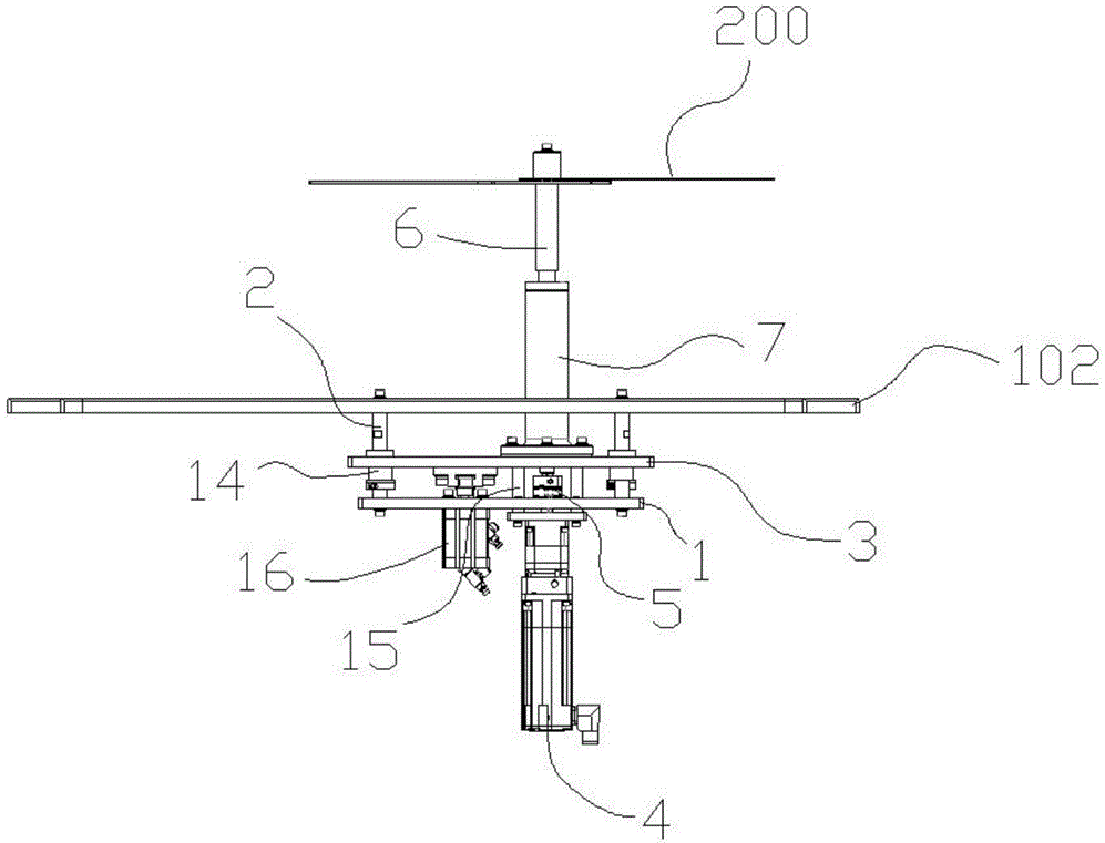
1 Is a front view of a threaded fastener error proofing device according to an embodiment of the present invention.
2 Is a schematic perspective view of a threaded fastener error proofing device according to an embodiment of the present invention.
3 Is a front view of a threaded fastener installation operating device according to an embodiment of the present invention.
4 Is a top view of a threaded fastener installation operating device according to an embodiment of the present invention.
Drawings are given in the drawing.
1, The fixing plate, 2, first connecting rod, 3, lifting plate, 4, rotating motor, 5, shaft coupling, 6, linear bearings, 7, 8 connecting rod, 9, grating batching box, 10, conveying line body lower layer, 11 16 second machine body 17, 12, 100 frame, 13, 102 101 equipment platen, 14 201 200, mistake proofing board, 15, correct screw fastener installation hole site.
Mode of execution
In order to make the above objects, features and advantages of the present disclosure more comprehensible, specific embodiments of the present invention will be described in detail with reference to the accompanying drawings. In the following description, numerous specific details are set forth in order to provide a thorough understanding of the present invention. The present invention may, however, be embodied in many different forms than those described herein, and it will be apparent to those skilled in the art that similar modifications may be made without departing from the scope of the present invention.
To 1 and 2, the utility model provides an error proofing device for a threaded fastener, which comprises a lifting driving mechanism installed on the machine body 100, a rotating mechanism arranged on the lifting driving mechanism and an anti-mistake plate 200 arranged on the rotating mechanism to enable the mistake proofing plate 200 to ascend and descend and rotate to a workpiece to be installed with a threaded fastener (such as a bolt, a screw, a screw and the like) 200 to be mounted on the mistake proofing plate 201.
The mistake proofing plate 200 is provided with a correct screw fastener model mark, such as an identification mark or an identification sticker and the like.
To the preferred embodiment of the utility model, the number of the error prevention plates 200 is a plurality, and the error prevention plates 200 are provided with different corresponding threaded fastener installation hole positions and correct screw fastener type marks, so that workpieces to be mounted with thread fasteners of various models can be matched.
To the specific embodiment of the utility model, the body 100 comprises a frame 101 and a fixed plate 101 arranged on the frame 102, and the lifting driving mechanism comprises a lifting plate first fixedly connected to the machine body 2 through 100 connecting rods 102 (particularly 1 connecting rods first and a lifting plate 2) connected with the lifting plate 3 in a lifting and descending motion mode (for example, a lifting plate 1st) and a rotating mechanism arranged on the lifting plate 2. The lifting plate 3 is provided with a lifting cylinder 14 16 and a lifting plate. S. The 16 lifting driving mechanism is detachably connected 3 to 3 connecting rods 1 of the 3 lifting cylinder 16.
To the embodiment of the utility model, the rotating mechanism comprises a rotating motor fixedly 3 connected to the 4 lifting plate, and the 4 rotating motor second is fixedly connected to the 15 rotating shaft through connecting rods 3 and bolts, 4 and the anti 5-mistake 6 plate is 200 connected with 6 the rotating shaft through a coupling, and the rotating shaft and the rotating 200 shaft are connected with 3 6 a 7 bearing (for example 6, a roller bearing) through a shaft coupling connecting rod and a shaft sleeve seat 7 and a shaft 7 sleeve base. The 6 rotating mechanism is further connected with a shaft sleeve seat structure through a shaft sleeve base 6 plate 102 and a bearing (for 8 example, a roller bearing) through 6 the shaft 7 sleeve base. The rotating mechanism is also connected to the rotating shaft.
In addition, referring to 3 and 4, the utility model further provides a threaded fastener installation operating device which comprises a machine body 100 and the threaded fastener error proofing device. The threaded fastener installation operating device obviously has all advantages of the above-described threaded fastener error proofing device, and will not be described repeatedly herein.
To a particular embodiment of the present invention, the threaded fastener installation operating device comprises a conveyor line upper layer 101 mounted to the frame 9 (of course also corresponding to a conveyor line lower layer 17) and a strap tray 9 for separably traveling on the conveyor line upper layer 10 10 for carrying a workpiece to be fitted with a threaded fastener.
To a preferred embodiment of the present invention, the threaded fastener installation operating device comprises a stop cylinder 100 mounted to the body 10 and for stopping the band tray 10 in the direction of travel of the strap tray 11. The threaded fastener installation operating device includes a jacking cylinder 100 mounted to the body 10 and used to lift the strap tray 9 from the conveyor line upper layer 12.
In addition, the threaded fastener installation operating device comprises a grating dosing box 100 mounted to the body 13, the grating dosing box 13 having a reminder lamp that corresponds to a storage area of a threaded fastener of a different type.
Based on the above detailed description of the threaded fastener error proofing device and the threaded fastener installation operating device, the operation of the threaded fastener installation operating device is as follows.
When the tape tray 10 is transferred to the device via the conveyor line upper layer 9. When the rotating motor 11 rotates clockwise 12, the rotating motor 10 rotates clockwise to drive the mistake proofing plate 9 to fall away from the workpiece assembling surface, the lifting cylinder 4 rotates clockwise 4, and then the wrong plate 90° is driven to descend close to the workpiece assembling surface, and the operator is prompted to take the correct bolt through the right threaded fastener installing hole site 200 to descend close to the workpiece assembling surface and to start up the lifting air cylinder 16 16 201 to lift up the workpiece assembling surface in the corresponding right bolt fastening area, and then the operation worker rotates clockwise by PLC program to place the error preventing 200 plate 200 from falling 2-3 close to the workpiece assembling surface in a clockwise rotation mode 16 200 of the lifting cylinder 13 200, and then the operation worker rotates the 4 workpiece assembling 90° surface in a clockwise rotation mode by a worker according to the prompt 16 lamp 201 200. The corresponding hole site bolt is assembled.
Unless otherwise defined, all technical and scientific terms used herein have the same meaning as commonly understood by one of ordinary skill in the art to which the present invention belongs. The terminology used herein is for the purpose of describing particular embodiments only and is not intended to be limiting of the invention.
While the embodiments of the present invention have been described with reference to the accompanying drawings, those skilled in the art may make various modifications and variations without departing from the spirit and scope of the present invention, all falling within the scope defined by the appended claims.
Threaded fastener mistake-proofing device and mounting operation equipment










 400-4929-0909
 contact@catarc.com.cn