Content of the invention
The invention aims to provide a water injection rod assembly which solves the problem that a special-shaped water injection hole is bent in the front process. The sealing problem of the pipe end bevel caused by profiling or pre-forming is solved.
In order to solve the technical problems, the invention is realized by the following technical scheme.
The invention provides a water injection rod assembly which comprises the water injection rod assembly.
The water injection rod comprises a groove, wherein the groove is arranged at one end of the water injection rod.
When the lower hemisphere is coaxial with the water injection rod, the upper part of the lower hemisphere is flush with the water outlet, and the lower part of the lower hemisphere is tightly attached to the inner wall of the groove.
The steering hard top head is provided with a hole in the axial direction, and the hole penetrates through the top column and the lower hemisphere.
In one embodiment of the invention, the lower hemisphere is provided with through holes and column holes, and the through holes are connected with the column holes.
In one embodiment of the invention, the axial projection of the through hole is circular, and the radial projection of the through hole is trapezoidal.
In one embodiment of the invention, the top post is provided with an opening, the opening is connected with the through hole, the top of the top column is provided with an inclined conical surface, the circumferential edge of the inclined conical surface is provided with a chamfer, and the inclined conical surface forms a step with the top of the lower hemisphere.
In one embodiment of the invention, a central axis of the top pillar coincides with a central axis of the lower hemisphere, and a diameter of the top pillar is smaller than a diameter of the lower hemisphere.
In one embodiment of the invention, the lateral projection of the lower hemisphere is semicircular.
In one embodiment of the invention, the top post includes an aperture through which the aperture passes.
In one embodiment of the invention, the sealing ring is disposed in the top pillar, and a bottom surface of the sealing ring is attached to a top of the lower hemisphere.
In one embodiment of the invention, the water injection hole comprises:
The first Water injection hole, it sets up in the lateral wall of water injection pole.
The second Water injection hole, it connects first water injection hole.
In one embodiment of the invention, a bolt is further included, the bolt is a hollow structure, and the bolt is inserted in the hole of the steering hard top head.
To sum up, the invention provides a water injection rod assembly which is simple and simple in sealing structure, and the manufacturing cost and the production cost are reduced. The device is provided with a steering hard top head with an adjustable angle, and can meet the machining shape of a to-be-machined part and enhance the sealing effect of the port to be machined. The device can automatically adjust the feeding amount of the inner and outer sides according to the internal stress of the material to be machined, and solves the phenomenon of wrinkling of the workpieces to be processed and the external cracking phenomenon in the expanding process of the to-be-machined parts.
Of course, any product embodying the present invention does not necessarily need to reach all of the advantages described above at the same time.
Description of drawings
In order to more clearly illustrate the technical solution of the embodiments of the present invention, it will be apparent that the accompanying drawings in the following description are merely some embodiments of the present invention, and other drawings may be obtained according to these drawings without paying any inventive work to those of ordinary skill in the art.
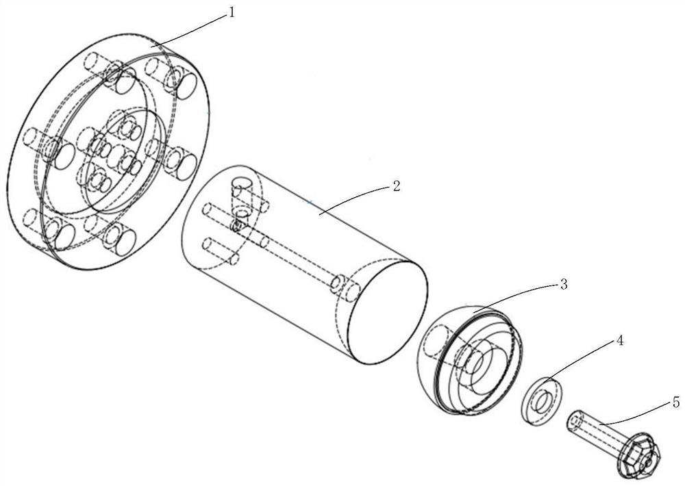
1 Is an exploded view of a water injection rod assembly in an embodiment.
2 Is a side view of a water injection rod assembly in an embodiment.
3 Is a schematic view of an adapter plate in an embodiment of a water injection rod assembly.
4 Is a schematic view of a water injection rod assembly according to an embodiment of the present invention.
5 Is a side view of a water injection assembly in an embodiment of a water injection rod assembly.
6 Is a top view of a water injection rod in an embodiment of a water injection rod assembly.
7 Is a schematic view of a steering hard top head in an embodiment of a water injection rod assembly.
8 Is a side view of a steering hard top head in an embodiment of a water injection rod assembly.
9 Is a schematic structural view of a steering hard top matched water injection rod in an embodiment of the water injection rod assembly.
10 Is a schematic view of a steering hard top head adjusting axial maximum angle in one embodiment of a water injection rod assembly.
11 Is a screw schematic view of a water injection rod assembly in an embodiment.
12 Is a schematic view of one embodiment of a water injection rod assembly in combination with a workpiece to be machined.
In the drawings, the list of components represented by the respective reference numerals is as follows.
1 Adapter plate 23 Groove 32 top column
11 first Through hole 231 water outlet 321 opening
12 second Through hole 24 fixing hole 322 inclined conical surface
2 Water injection rod 3 turns to hard top head 33 step
21 Sprue 3 A hole 4 sealing ring
211 1st-way pipe 31 lower hemisphere 5 bolt
212 2nd-way pipe 311 lower part 51 1st-hole
22 Water injection hole 312 upper part A raised area
221 first Water injection hole 313 through hole B sunken area
222 second Water injection hole 314 column hole
Mode of execution
, Technical solutions in the embodiments of the present invention will be apparent from the accompanying drawings in the embodiments of the present invention. , It will be apparent that the described embodiments are only part of the embodiments of the present invention, and not all of the embodiments. All other embodiments obtained by a person of ordinary skill in the art based on the embodiments of the present invention without creative efforts shall fall within the protection scope of the present invention.
It should be noted that the illustration provided in this embodiment illustrates only the basic idea of the present invention in a schematic manner, and only the components related to the present invention rather than the number, shape, and size of the components in actual practice are shown.
When the special-shaped water injection hole is expanded, the special-shaped water injection hole needs to be sealed, and the sealing mode of the special-shaped water injection hole can be divided into two types.
The sealing mode is poor in sealing effect, high in requirement on equipment control precision and incapable of meeting the sealing of a bulging medium in a pipe end inclined port state of a machined part.
In addition, due to the fact that the used polyurethane is easy to damage, frequent replacement is needed, equipment is easy to stop, the sealing space and the position are required to occupy more sizes of pipes, and at least 40 mm materials are longer than the hard seal in the same condition, and the cost is increased obviously.
To FIG. 1, the present invention provides a water injection rod assembly comprising: an adapter plate 1, a water injection rod 2, a steering hard top head 3, a seal ring 4, and a bolt 5. The adapter plate 1 is fixedly connected with the water injection rod 2, the steering hard top head 3 is embedded at one end of the water injection rod 2, the sealing ring 4 is arranged in the steering hard top head 3, and the bolt 5 penetrates through the steering hard top head 3 and is inserted into the water injection rod 2.
To FIGS 1 and 2, in an embodiment of the present invention, the adapter plate 1 is mounted on the flange surface of the sealing cylinder, and the water injection rod 2 is mounted on the flange surface of the adapter plate 1 by screws, and the steering hard top head 3 is disposed inside the steering hard top head 2. The bolt 4 passes through the steering hard top head 3 and the sealing ring 5 4 3 in this order.
Please refer to FIG. 2 and FIG. 3. In an embodiment of the invention, the adapter plate 1 is shaped, for example, as a cylinder, conveniently for mounting an oil cylinder. The adapter plate 1 is, for example, an oil cylinder adapter plate, 1 through holes first and 11 through holes second are formed in the adapter plate 12, first through holes 11 penetrate through the adapter plate 1, and the adapter plate 1 is located at a larger ring layer position. The first Through-holes 11 are, for example, at least six, first through-holes 11 for fastening several bolt members on the flange face of the sealing cylinder. The second Through-holes 12 are provided adjacent first through-holes 11, with respect to first through holes 11 and on the inner ring, second through holes 12 for fastening several bolt members. On the adapter plate 1.
To FIG. 1, FIG. 4 and FIG. 5, in an embodiment of the present invention, the water injection rod 2 is fixed to the adapter plate 1 through several bolt members, and the water injection rod 2 is configured to pressurize the interior of the workpiece to be machined. Water injection rod 2 can include water injection port 21, water injection hole 22, recess 23 and fixed orifices 24, water injection port 21 perpendicular connection water injection hole 22, water injection hole 22 connect recess 23, and fixed orifices 24 are provided on both sides of water injection hole 22.
As shown 1 through 5, there is shown. The water injection port 21 is arranged on one side of the adapter plate 1 to facilitate connection of supercharging equipment. Water inlet 21 is arranged at one end of water injection rod 2, penetrates through water injection rod 2 vertically, and water injection nozzle 21 is externally connected with high pressure water pipe for conveying liquid into water injection hole 2 in water injection rod 22. The water injection port 21 may include first through pipes 211 and second through pipes 212, first through pipes 211, and second through pipes 212. The first The tube 211 is in the form of a hollow cylinder for injecting high pressure liquid. The upper part second of the pipe 212 is a hollow cylinder, and the lower part second of the pipe 212 is a hollow cone. Wherein. The second Through-tube 212 has a diameter smaller than the diameter second of the lower part of tube 212, facilitating high-pressure liquid build-up into injection hole 22. The second Through pipe 212 runs through the upper surface of water injection hole 22, second through pipe 212 transmits the expansion type medium that flows into through injection nozzle 21 into water injection hole 22.
As shown 4 through 5, FIGS. Water injection hole 22 is arranged in water injection rod 2, and water injection hole 22 is used for interior expansion type medium of circulation hole. Water holes 22 may include first water injection holes 221 and second water injection holes 222, first water injection holes 221 and second water injection holes 222, 5 water injection holes first are connected 212 through pipes second high pressure liquid from 212 pipe second flows through 212 water injection holes first through 221 water injection holes second 222, and high pressure liquid is conveyed to corresponding bolt parts. The first Water injection hole 212 is less than second water injection hole 222's diameter, is convenient for second water injection hole 222 accommodation bolt spare for second water injection hole 222 is used for. One end of the receiving bolt member.
As shown 1 and 4, the groove 23 is provided at the other end inside the water injection rod 2 for receiving and mounting the steering hard ejection head 3. The groove 23 is semicircular, the opening of the groove 23 is a water outlet 231, the diameter of the water outlet 231 is equal to that of the water injection rod 2, the water outlet 231 is conveniently connected to the hard top head 3, and the outer wall of the steering hard top head 3 is closely attached to the inner wall of the groove 23.
As 5 and 6, the fixing hole 24 is formed at one end inside the water injection rod 2 and adjacent to the water injection port 21, and a plurality of bolt members are mounted on the adapter plate 24 through the fixing holes 1. A fixing hole 24 is provided around the water injection hole 22 to center the water injection hole 22, and the fixing hole 24 is scattered around the water injection hole 22. The fixing member 24 is for mounting a bolt member. The number of fixing holes 24 is, for example, at least four so that the bolt member can be stably fastened to the adapter plate 1.
Please refer to FIG. 7 and FIG. 9. In one embodiment of the present invention, the steering hard ejection head 3 is embedded at one end inside the water injection rod 2, and when the water injection rod assembly drives the end surface close to the workpiece to be machined via the oil cylinder, the central axis of the steering hard top head 3 3 and the water injection rod 2 are in a coaxial state. As shown 9, the steering hard top head 3 may be integrally formed, and when the integrally formed steering hard top head 3 and the water injection rod 2 are tightly coupled, the steering hard top head 3 may closely contact one end of the water injection rod 2 to facilitate improving the sealing property of the steering hard top head 3. Further, the steering hard top head 3 may include a lower hemisphere 31 and a top pillar 32. The top pillar 32 is disposed on the lower hemisphere 31, the lower hemisphere 31 is connected to the top pillar 32, and may be connected to each other. The lateral projection of the lower hemisphere 31 is semicircular, and when the central axis of the lower hemisphere 31 coincides with the central axis of the top post 32, the steering hard top head 3 keeps horizontal, so that the expanding medium smoothly flows into the hole 3A of the steering hard top head 3. Since the lower hemisphere 31 and the top post 32 are asymmetrical, the diameter of the top post 32 is equal to that of the lower hemisphere 31, and the lower hemisphere 31 and the top post 32 are combined to form an integrally formed steering hard top head 3. When one end of a to-be-machined part is likely to have an oblique opening phenomenon. Under the action of the reaction force of the pipe end of the to-be-machined part, as the lower hemisphere 31 rotates to a certain angle, the top column 32 and the lower hemisphere 31 rotate synchronously, so that the integrally formed steering hard top head 3 can be formed. At this time, the steering hard top head 3 automatically adjusts the axial direction so that the outer wall of the lower hemisphere 31 fits tightly against the inner wall of the groove 23, and the sealing property of the bonding surface between the hard top head 3 and the water injection rod 2 is realized. However, the steering hard top head 3 can automatically adjust the axial direction according to the actual situation of the internal stress of the material to be machined, and realize the compensation amount on the inner side of the outer side. The problem of inside creping, external fracture in the bent pipe shaping effectively is solved.
9 - Is shown 10. In an embodiment of the present invention, when the water injection rod assembly is driven toward the end surface of the workpiece to be machined via the cylinder, the lower portion 3 of the steering hard top head 0° fits tightly against the center axis of the water injection rod 3, and the lower portion 2 and the upper portion 3 31 of the lower hemisphere 231 312 31 coincide with the 312 water outlet 311 such that 2 the upper portion 23 is positioned between the water injection rod 311 and the replacement part. , The steering hard top head 3 is provided with holes 3A in the axial direction. The hole 3A may include a through hole 313, a pillar hole 314 and an opening 321, through 313 connecting the pillar hole 314, and through the lower hemisphere 31 to receive a space for receiving a bolt member. The radial projection shape of the through hole 313 may be trapezoidal, and the axial projection is circular, and the central axis of the bolt member in the receiving space may still overlap the original central axis of the lower portion 311 after the lower portion 311 is rotated, so that the lower portion 311 may be rotated to a certain angle. When the water injection rod assembly drives the end face close to the workpiece to be machined via the oil cylinder, the central axis of the column hole 314 coincides with the central axis of the through hole 313. The central axis of the top post 32 used for coupling the workpiece to be processed is provided with an opening 321, the opening 321 is connected with the column hole 314, and the opening 321 can inject the high pressure liquid flowing through the column hole 314 into a machining mold cavity to be machined. The top side of the top post 32 is provided with an inclined conical surface 322, and the inclined cone 322 is convenient for being sleeved on the top column 32 more easily. The circumferential edge of the inclined cone 322 is provided with a chamfer 323, the chamfer 323 enables the inner wall of the workpiece to be machined to smoothly slide over the inclined cone 322, and the workpiece to be machined is conveniently sleeved on the top column 32. The inclined cone 322 has a step 31 between the outer side wall and the top of the lower hemisphere 33. The step 33 connects the top post 32 to the lower hemisphere 31, and when the workpiece to be machined covers the step 33 and the upper surface of the top post 32 and the side thereof, the port to be machined is attached to the port of the water injection rod 2 more closely.
Please refer to FIG. 2 and FIG. 9. In an embodiment of the present invention, after a desired condition is formed in an oil cylinder connected to the adapter plate 1, the pipe orifice of the to-be-machined part is connected to one end of the water injection rod 3 through the steering hard top head 2. The steering hard top head 2 is rotated to deviate from the axis by a certain angle in the water injection rod 3, and the expansion type medium is installed on the water injection rod 3 through the steering hard top head 3 3 at a certain angle in the steering hard top head 2 5. The pressure between the workpiece and the workpiece die is slowly unloaded until the unloading is finished, the machined part die cavity is opened, the machined part is taken out, and the expansion process is completed. Since the force of the sealing ring 4 can return the steering hard top head 3 to the initial position, the axial direction of the steering hard top head 3 and the axial direction of the water injection rod 2 are in a coaxial state, and the next expansion process is awaited.
To FIGS 2 and 9, in the embodiment of the present invention, the seal ring 4 is embedded in the steering hard top head 3 and located at the bottom of the opening 32 of the top pillar 321, and the seal ring 4 fits the upper surface of the lower hemisphere 31 such that the seal ring 4 is in the middle of the bolt 5 head and the knuckle head 3. The sealing ring 4 is used for improving the space sealing between the steering hard top head 3 and the to-be-machined part and is simple in sealing structure.
As shown 9, the bolt 5 of the hollow structure is inserted into the center axis of the steering hard top head 3 such that the tail of the bolt 5 is located in the through hole 31 and the column hole 313 of the lower hemisphere 314, and the head of the bolt 5 is engaged in the opening 32 of the top pillar 321. The bolt 5 is provided with first holes 51 through which first holes 51 penetrate the center axis of the bolt 5, first holes 51 for inputting liquid to the inside of the workpiece to be machined. The bolt 5 may be, for example, a hexagonal flange bolt, and the bolt 5 is used to fasten the steering hard top head 3 with the water injection rod 2.
To FIG. 1, FIG. 5 and FIG. 9, in one embodiment of the present invention, the adapter plate 1, the water injection rod 2, the steering hard ejection head 3, the seal ring 4, and the bolt 5 are combined to form a water injection rod assembly. The water injection rod assembly drives the end face close to the workpiece to be machined via the oil cylinder, so that the axial direction of the steering hard top head 3 and the water injection rod 2 are in a coaxial state. The top pillar 3 of the steering hard top head 32 is introduced into the pipe wall of the workpiece to be machined, and the step 3 of the steering hard top head 33 gradually adheres to the pipe end of the workpiece to be machined as the oil cylinder continues to advance.
In addition, when the water injection rod 2 is formed into a proper sealing position, the pressurizing device injects the liquid into the blank pipe 21 through the water injection nozzle 2, and the liquid flows through 5 holes first of the bolt 51.
As shown 9. When the pipe end of the to-be-machined part is in an inclined state, the step 3 of the steering hard top head 3 can automatically adjust the axial direction and the steering hard top head 0 - 10° can be automatically adjusted. 3. The steering hard top head 5° can be automatically adjusted by 6°, 7°, 8°, 3, and the steering hard top head 7°. 33 3 can be automatically adjusted to the maximum angle range of the workpieces to be machined to achieve the sealing condition, and meanwhile, the local compression ratio is larger. 4 Furthermore, the integral sealing performance of the water injection rod assembly is improved.
Please refer 1 and FIG. 10. In one embodiment of the present invention, the oil cylinder drives the water injection rod 2 so that the steering hard top head 3 is inserted into an end opening part of a to-be-machined part requiring a high-pressure expansion type, and the oil cylinder feeding position is adjusted so that the lower hemisphere 3 of the steering hard top head 31 is fully attached to the inner wall and the end part to be machined. The high-pressure liquid is injected into the water injection rod 21 through the water injection nozzle 2 through the high-pressure pipeline, and the inner part of the to-be-machined part is fully applied to the molding die cavity to finish expansion of the to-be-machined part. Step.
Please refer 1, FIG. 9 and FIG. 10, in another embodiment of the present invention, since L-type to-be-machined part needs to be increased in an inclined state before expanding L type to be machined, L type of workpiece to be machined is in an inclined state, so that the raised area L of L type to be machined is cracked, and the concave area A of L B type to be machined is wrinkled.
As shown 10, the end surface of the steering hard top head L automatically adjusts the axial direction according to the actual conditions of the material component and the internal stress of L to be machined, so as to increase the thickness of the pipe wall 3 to treat the workpiece. L. The inner side of 10 mm-shaped workpiece to be machined is increased to L to prevent the bulging area 3 mm A from cracking phenomenon and wrinkle phenomenon in the concave area B L.
To 1, FIG. 9, and FIG. 10, in another embodiment of the present invention, since S-type workpieces to be machined are before the expansion process, a bend is also required to be increased in the prost order. When the water injection rod assembly rises S type to be machined, the pipe end opening of S type to be machined after the return bend is in an inclined state, causing S type ports to be machined to have oblique openings, so that the bulging region S of A type to be machined has a cracking phenomenon and S type of sunken area B to be machined is wrinkled.
As shown 10, the end face of the steering hard top head S automatically adjusts the axial direction according to the actual conditions of the material component and the internal stress of S to be machined, so as to increase the thickness of the pipe wall 3 to treat the workpiece. S, to prevent the bulging area 10 mm from cracking. The concave area S generates a wrinkle phenomenon S in accordance with the actual conditions of the material A component and the internal stress of B the 3 mm-type workpiece to be machined.
To sum up, the invention provides a water injection rod assembly which is simple and simple in sealing structure, and the manufacturing cost and the production cost are reduced. The device is provided with a steering hard top head with an adjustable angle, and can meet the machining shape of a to-be-machined part and enhance the sealing effect of the port to be machined. The device can automatically adjust the feeding amount of the inner and outer sides according to the internal stress of the material to be machined, and solves the phenomenon of wrinkling of the workpieces to be processed and the external cracking phenomenon in the expanding process of the to-be-machined parts.
The preferred embodiments of the present invention disclosed above are merely used to help explain the present invention. It is to be understood that both the foregoing general description and the following detailed description are exemplary and explanatory and are intended to provide further explanation of the invention as claimed. , Many modifications and variations can be made in light of the present specification. These embodiments are selected and specifically described in this specification to better explain the principles and practical applications of the present invention, and thus enable those skilled in the art to understand and utilize the present invention well. The invention is limited only by the claims and their full scope and equivalents.


 400-4929-0909
 contact@catarc.com.cn

