Hereinafter, the present invention will be described with reference to the related drawings. An embodiment of the present invention is shown in the drawings. If a part is considered to be "connected" to another part, that part may be directly connected to the other part, or there may be intervening parts at the same time. Unless otherwise defined, all technical and scientific terms used in the present invention have the same meaning as commonly understood by one of ordinary skill in the art of the present invention. The terms used herein are for illustration purposes only and are not intended to limit the invention. The term "and / or" as used in the present invention includes any and any combination of related listed one or more items.
Manual wipers and automatic wipers on automobiles often select the operation by manually switching the electric switch. Manual wipers and automatic wipers have many drawbacks in the actual usage process, such as: 1. 1. A manual wiper is usually set with six operating gears, and when the driver performs an operation to adjust the wiping motion speed, it is necessary to manually and accurately adjust to the exact desired gear, and the intermediate gear is exceeded. Since the gears are adjusted in the order of the gears, the operation is complicated and the execution efficiency is low. 2. The wiping motion speed of the automatic wiper is determined by the magnitude of the rainfall detected by the rainfall sensor, but the requirements for the wiping motion speed differ depending on the individual driver, and the same driver has different requirements for the wiping motion speed. Even if there is different time and physical condition, the requirement for wiping movement speed is different for the same amount of rain, but the wiping movement speed of the automatic wiper is controlled only by the amount of rain, and the driver of the car actively adjusts it. Can not.
FIG. 1 is a flowchart of a wiper smart control method according to an embodiment. As shown in FIG. 1, the wiper smart control method according to the present embodiment includes the following steps.
Step 110 is to switch the operating state of the wiper to the automatic wiping operating state or the manual wiping operating state according to the received wiper operating state switching signal.
The automatic wiping operation state means that the wiping movement speed of the wiper automatically changes as the amount of rainfall sensed by the rainfall sensor changes, and the manual wiping operation state means that the wiping movement speed of the wiper adjusts. It is steady after completion and does not change as the amount of rainfall changes.
In step 120, when the wiper operates in the automatic wiping operation state, the wiping movement speed automatically changes as the amount of rain detected by the rain amount sensor changes, and the wiping movement speed adjustment signal output by the manual operation module. Is received, the current wiping motion speed is adjusted according to the wiping motion speed adjustment signal, and the correspondence between the adjusted wiping motion speed and the amount of rainfall when the wiping motion speed adjustment signal is received is used as a reference, and then. It adjusts the wiping motion speed corresponding to different rain magnitudes, and the wiping motion speed automatically changes as the magnitude of the rainfall sensed by the rainfall sensor changes.
In this embodiment, the manual operation module is a module for adjusting the wiping motion speed provided to the user.
In step 130, when the wiper switches from the automatic wiping operation state to the manual wiping operation state, the current wiping movement speed of the wiper is locked to the wiping movement speed of the manual wiping operation state, and the wiper operates in the manual wiping operation state. When the wiping motion speed adjustment signal output by the manual operation module is received, the current wiping motion speed is adjusted according to the wiping motion speed adjustment signal.
The wiping control method according to the present embodiment includes a manual wiping adjustment function and a rain detection automatic wiping adjustment function at the same time, and two types of functions, the manual wiping adjustment function and the automatic wiping adjustment function, can operate each other, that is, When the wiper operates in the automatic wiping operation state, the driver can manually adjust the preset wiping motion speed according to the amount of rainfall until the wiping motion speed required by the driver is reached. The movement speed is more matched to the driver's current requirements, the driver's individual differences are met, and the wiping movement speed of the wiper is more humane, and the automatic wiping operation state is used at any time. The current wiping movement speed can also be locked to the wiping movement speed of the wiper in the manual wiping operation state, and when the wiper operates in the manual wiping operation state, the wiping movement speed of the wiper is the wiping movement required by the driver. When not speed, the driver can adjust the current wiping motion speed until the wiping motion speed required by the driver is reached, and realizes multi-step adjustment of the wiping motion speed of the wiper, which is easy to operate and wiper. The efficiency of adjusting the wiping movement speed is improved.
In one embodiment, the wiping motion speed adjustment signal is used to instruct the wiping motion speed to be increased or decreased, and adjusting the current wiping motion speed in response to the wiping motion speed adjusting signal is wiping. When the motion speed adjustment signal is instructed to increase the wiping motion speed, the motor rotation speed of the wiper corresponding to the current wiping motion speed is increased by the rotation speed change value corresponding to the default speed control resolution, and the wiping motion is performed. When the speed adjustment signal is instructed to reduce the wiping motion speed, the motor rotation speed of the wiper corresponding to the current wiping motion speed is reduced by the rotation speed change value corresponding to the default speed control resolution, and the default. The speed control resolution of is the rotation speed change value of the motor rotation speed of the default wiper.
In one embodiment, the wiping motion speed adjustment signal is used to instruct the wiping motion speed to be increased or decreased, and further before adjusting the current wiping motion speed in response to the wiping motion speed adjusting signal. , Including receiving the speed control resolution setting signal output by the manual operation module and setting the speed control resolution according to the speed control resolution setting signal, the speed control resolution is the change in the rotation speed of the motor rotation speed of the wiper. Adjusting the current wiping motion speed according to the wiping motion speed adjustment signal is a value, and when the wiping motion speed adjustment signal instructs to increase the wiping motion speed, the motor of the wiper corresponding to the current wiping motion speed. When the rotation speed is increased by the rotation speed change value corresponding to the speed control resolution after setting and the wiping motion speed adjustment signal is instructed to decrease the wiping motion speed, the motor of the wiper corresponding to the current wiping motion speed. This includes reducing the rotation speed by the rotation speed change value corresponding to the speed control resolution after setting.
Another embodiment provides a smart control method of the wiping, which switches the wiping operating state to an automatic wiping operating state or a manual wiping operating state in response to a received wiping operating state switching signal. The automatic wiping operation state means that the wiping motion speed of the wiper automatically changes as the magnitude of the rain amount sensed by the rain amount sensor changes, and the manual wiping operation state means the wiping of the wiper. It includes the fact that the kinetic velocity is steady after the adjustment is completed and the wiping kinetic velocity does not change as the amount of rainfall changes.
When the wiper operates in the automatic wiping operation state, the wiping motion speed preset according to the amount of rainfall is not the wiping motion speed required by the driver, until the wiping motion speed required by the driver is reached. The current wiping motion speed is adjusted, and the said adjustment is to realize the purpose of adjusting the wiping motion speed by adjusting the rotation speed of the motor of the wiper.
When the wiper operates in the manual wiping operation state, the driver manually adjusts the current wiping motion speed until the wiping motion speed required by the driver is reached, and the adjustment is the rotation speed of the wiper motor. By adjusting, the purpose of adjusting the wiping movement speed is realized.
When the wiper switches from the automatic wiping operation state to the manual wiping operation state, the current wiping movement speed of the wiper is locked to the wiping movement speed in the manual wiping operation state, and the wiping movement speed in the manual wiping operation state is requested by the driver. If it is not the wiping motion speed, the current wiping motion speed is adjusted until the wiping motion speed required by the driver is reached, and the adjustment is to adjust the wiping motion speed by adjusting the rotation speed of the motor of the wiper. To achieve the purpose.
When the wiper switches from the manual wiping operation state to the automatic wiping operation state, the wiper moves at a preset wiping motion speed according to the amount of rain, and the preset wiping motion speed according to the amount of rain is the driver. If it is not the wiping motion speed required by the driver, the current wiping motion speed is adjusted until the wiping motion speed required by the driver is reached, and the adjustment is the wiping motion speed by adjusting the rotation speed of the motor of the wiper. Is to achieve the purpose of adjusting.
In one embodiment, if the preset wiping motion speed according to the amount of rainfall is not the wiping motion speed required by the driver, the current wiping motion speed is set until the wiping motion speed required by the driver is reached. To adjust, the current wiping motion speed is adjusted until the wiping motion speed required by the driver is reached, if the preset wiping motion speed according to the amount of rainfall is not the wiping motion speed required by the driver. Adjust and adjust the wiping movement speed corresponding to the subsequent different rain amount based on the correspondence between the wiping movement speed when the driver's required wiping movement speed is reached and the amount of rainfall. Including. As a result, the operating state of the wiping is still in the automatic wiping operating state, and for the subsequent change in the amount of rainfall detected by the rainfall sensor, the wiping motion speed responds to the change in the amount of rainfall according to the new standard. Since new changes are made automatically, there is no need to manually adjust the wiping speed each time the rainfall changes, and the degree of smartness is high.
In one embodiment, if the preset wiping motion speed according to the amount of rainfall is not the wiping motion speed required by the driver, the current wiping motion speed is set until the wiping motion speed required by the driver is reached. Adjusting is according to the speed control gear stage selected by the driver and the default speed control resolution, if the preset wiping motion speed according to the amount of rainfall is not the wiping motion speed required by the driver. Adjust the current wiping motion speed until the wiping motion speed required by the driver is reached, or the preset wiping motion speed according to the amount of rainfall is the wiping motion speed required by the driver. If not, the speed control includes adjusting the current wiping motion speed until the wiping motion speed required by the driver is reached according to the speed control resolution selected by the driver and the speed control gear stage selected. The resolution is the number of rotations at which the motor rotation speed of the wiper changes per minute (that is, the change value of the rotation speed of the motor rotation speed of the wiper) for each speed adjustment operation.
In one embodiment, if the preset wiping motion speed according to the magnitude of rainfall is not the wiping motion speed required by the driver, the driver first adjusts the current wiping motion speed with the default governor resolution. If the driver feels that the adjustment range of the default governor resolution does not meet the requirements, select another governor resolution, and then if the driver selects the governor gear, drive. According to the speed governor gear stage and speed control resolution selected by the operator, the current wiping motion speed is adjusted until the wiping motion speed required by the driver is reached.
In one embodiment, if the wiping motion speed in the manual wiping operating state is not the wiping motion speed required by the driver, adjusting the current wiping motion speed until the wiping motion speed required by the driver is reached is not possible. If the wiping motion speed in the manual wiping operation state is not the wiping motion speed required by the driver, the wiping motion speed required by the driver is set according to the speed control gear stage selected by the driver and the default speed control resolution. Until it is reached, the current wiping motion speed is adjusted according to the speed control gear stage selected by the driver and the default speed control resolution, or the wiping motion speed in the manual wiping operation state is the wiping motion speed required by the driver. If not, depending on the speed control resolution selected by the driver and the speed control gear stage selected, the current wiping motion speed is set to the speed control resolution and the driver's choice until the wiping motion speed required by the driver is reached. The speed control resolution includes adjusting according to a selected speed control gear stage, and the speed control resolution is a rotation speed at which the motor rotation speed of the wiper changes per minute for each speed control operation.
In one embodiment, if the wiping motion speed in the manual wiping operating state is not the wiping motion speed required by the driver, the driver first chooses to adjust the current wiping motion speed with the default governor resolution. If the driver feels that the default governor resolution adjustment range does not meet the requirements, he or she manually selects another governor, and then the driver selects the governor gear. According to the governor gear and the governor resolution, the current wiping motion speed is adjusted until the wiping motion speed required by the driver is reached.
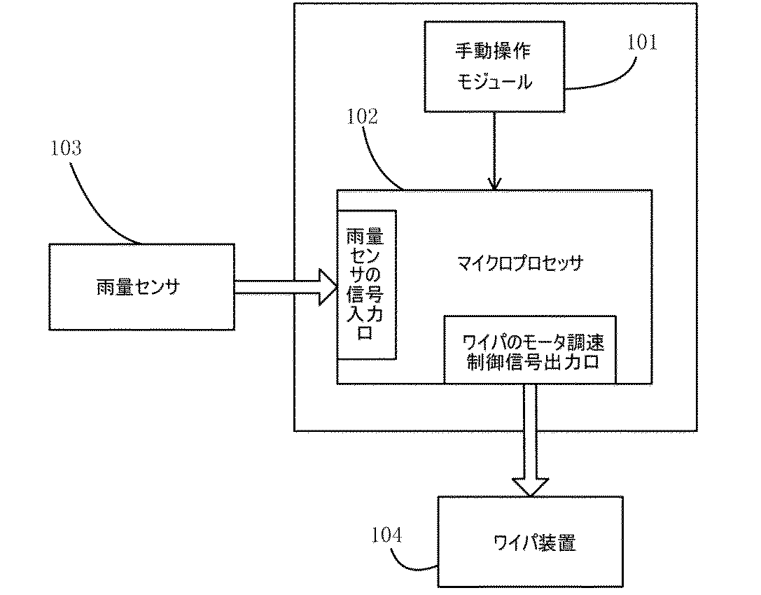
As shown in FIG. 2, FIG. 2 is a structural schematic diagram of a smart control device for a wiper according to an embodiment.
The present embodiment further discloses a wiper smart control device based on the wiper smart control method, which includes a manual operation module 101 and a microprocessor 102. In this embodiment, the microprocessor 102 refers to a microcontroller unit (Microcontroller Unit, MCU). The microprocessor 102 may be built in the smart control device, or may be a microprocessor in a control module or control unit mounted on an automobile. For example, the microprocessor 102 may be a vehicle body control module (Body) of an automobile. It may be a processor in Control Module, BCM).
In this embodiment, the manual operation module 101 is set to output the wiper operation state switching signal to the microprocessor 102, and the manual operation module 101 is further set to output the wiping motion speed adjustment signal to the microprocessor 102. The microprocessor 102 is configured to be connected to the rainfall sensor 103 and the wiper device 104, and the microprocessor 102 automatically wipes the wiper operating state in response to the wiper operating state switching signal output by the manual operation module 101. When the wiper is set to switch to the state or manual wiping operation state and the wiper operates in the automatic wiping operation state, the amount of rain detected in real time by the rain amount sensor according to the correspondence between the predetermined amount of rain and the wiping motion speed. By calculating the wiping motion speed corresponding to the magnitude of and outputting the wiping motion speed control signal corresponding to the wiping motion speed to the wiper device 104, the wiping operation corresponding to the wiping motion speed control signal is output to the wiper device 104. When the wiping motion speed adjustment signal output by the manual operation module 101 is received, the current wiping motion speed is adjusted according to the wiping motion speed adjustment signal, and the wiping motion speed is adjusted to be adjusted. When the motor speed control command of the wiper corresponding to the wiping movement speed is output to the wiper device 104 and the wiper switches from the automatic wiping operation state to the manual wiping operation state, the current wiping movement speed of the wiper is changed to the wiping movement in the manual wiping operation state. When locked to speed and the wiper operates in the manual wiping operation state, when it receives the wiping movement speed adjustment signal output by the manual operation module 101, it adjusts the current wiping movement speed according to the wiping movement speed adjustment signal. , The motor speed control command of the wiper corresponding to the adjusted wiping motion speed is output to the wiper device 104 so as to adjust the adjusted wiping motion speed.
In one embodiment, the microprocessor 102 further adjusts the current wiping movement speed in response to the wiping movement speed adjustment signal when the wiper operates in the automatic wiping operating state, and then adjusts the wiping movement speed and the wiping movement. Based on the correspondence with the magnitude of the rainfall when the speed adjustment signal is received, the wiping motion speed corresponding to the subsequent different magnitude of the rainfall is set to be adjusted.
In one embodiment, the wiping motion speed control signal is used to instruct the wiping motion speed to be increased or decreased, and the microprocessor 102 is present in the following aspects in response to the wiping motion speed adjustment signal. The wiping motion speed is adjusted and the motor speed control command of the wiper corresponding to the adjusted wiping motion speed is set to be output to the wiper device 104, and the wiping motion speed adjustment signal instructs to increase the wiping motion speed. Then, the motor rotation speed of the wiper corresponding to the current wiping motion speed is increased by the rotation speed change value corresponding to the default speed control resolution, and the motor speed control command of the wiper corresponding to the increased motor rotation speed of the wiper is issued. When it is output to the wiper device 104 and the wiping motion speed adjustment signal is instructed to reduce the wiping motion speed, the motor rotation speed of the wiper corresponding to the current wiping motion speed is changed to the rotation speed change value corresponding to the default speed control resolution. The motor speed control command of the wiper corresponding to the reduced motor rotation speed of the wiper is output to the wiper device 104, and the default speed control resolution is the rotation speed change value of the motor rotation speed of the default wiper. ..
In one embodiment, the manual operation module 101 is further set to output the speed control resolution setting signal to the microprocessor 102, and the microprocessor 102 further outputs the speed control resolution setting signal output by the manual operation module. It is set to receive and set the speed control resolution according to the speed control resolution setting signal, and the speed control resolution is a rotation speed change value of the motor rotation speed of the wiper, and the microprocessor 102 has the following aspects. , The current wiping motion speed is adjusted according to the wiping motion speed adjustment signal, and the motor speed control command of the wiper corresponding to the adjusted wiping motion speed is set to be output to the wiper device 104. When the adjustment signal is instructed to increase the wiping motion speed, the motor rotation speed of the wiper corresponding to the current wiping motion speed is increased by the rotation speed change value corresponding to the speed control resolution after setting, and the increased wiper When the motor speed control command of the wiper corresponding to the motor rotation speed is output to the wiper device 104 and the wiping motion speed adjustment signal is instructed to reduce the wiping motion speed, the motor rotation speed of the wiper corresponding to the current wiping motion speed is Is reduced by the rotation speed change value corresponding to the speed control resolution after setting, and the motor speed control command of the wiper corresponding to the reduced motor rotation speed of the wiper is output to the wiper device 104.
In one embodiment, the microprocessor 102 further receives vehicle travel information data including the vehicle travel speed, road surface unevenness, and environmental light outside the vehicle, and is sensed in real time by the vehicle travel information data and the rainfall sensor. It is set to set the wiping motion speed of the wiper according to the amount of rain.
In another embodiment, a wiper smart control device is provided. Referring to FIG. 2, the device includes a manual operation module 101 and a microprocessor 102. The manual operation module 101 is connected to the microprocessor 102, and the manual operation module 101 is set as follows. 1. 1. The wiper operation state switching signal is output to the microprocessor 102. 2. The wiping motion speed adjustment signal is output to the microprocessor 102. The microprocessor 102 is configured to be connected to the rainfall sensor 103 and the wiper device 104, and the processor 102 is further set as follows. 1. 1. The wiper operating state is switched to the automatic wiping operating state or the manual wiping operating state according to the wiper operating state switching signal output by the manual operation module 101. 2. When the wiper operates in the automatic wiping operation state, the wiping movement speed corresponding to the amount of rain detected in real time by the rain amount sensor 103 is calculated according to the correspondence relationship between the predetermined amount of rain and the wiping movement speed. By outputting the wiping motion speed control signal according to the wiping motion speed to the wiper device 104, the wiper device 104 is made to execute the wiping operation according to the wiping motion speed control signal, and the wiping motion speed at this time is the driver. If it is not the wiping motion speed required by, the wiper motor processes the wiping motion speed adjustment signal output by the manual operation module 101 and adjusts the wiping motion speed until the wiping motion speed required by the driver is reached. A speed control command is output to the wiper device 104, and the speed control command realizes the purpose of adjusting the wiping motion speed by adjusting the rotation speed of the wiper motor. 3. 3. When the wiper switches from the automatic wiping operation state to the manual wiping operation state, the current wiping movement speed of the wiper is locked to the wiping movement speed in the manual wiping operation state, and the wiping movement speed in the manual wiping operation state is requested by the driver. If it is not the wiping motion speed, the motor speed control command of the wiper is processed so as to process the wiping motion speed adjustment signal output by the manual operation module 101 and adjust the wiping motion speed until the wiping motion speed required by the driver is reached. Is output to the wiper device 104, and the speed control command realizes the purpose of adjusting the wiping motion speed by adjusting the rotation speed of the wiper motor. The manual wiping operation state is a state in which the wiping motion speed of the wiper is constant after the adjustment is completed, and the wiping motion speed is the rainfall. It does not change as the size of. 4. When the wiper operates in the manual wiping operation state, when the driver adjusts the current wiping movement speed, the microprocessor 102 processes the wiping movement speed adjustment signal output by the manual operation module 101, and the wiping requested by the driver. A wiper motor speed control command is output to the wiper device 104 so as to adjust the wiping motion speed until the motion speed is reached, and the speed control command adjusts the wiping motion speed by adjusting the rotation speed of the wiper motor. Achieve the purpose. 5. When the wiper switches from the manual wiping operation state to the automatic wiping operation state, the wiping of the wiper moves at a preset wiping motion speed according to the amount of rain, and the preset wiping motion speed according to the magnitude of the rain. If it is not the wiping motion speed required by the driver, the microprocessor 102 processes the wiping motion speed adjusting signal output by the manual operation module 101 and adjusts the wiping motion speed until the wiping motion speed required by the driver is reached. As described above, the motor speed control command of the wiper is output to the wiper device 104, and the speed control command realizes the purpose of adjusting the wiping motion speed by adjusting the rotation speed of the wiper motor.
In one embodiment, the microprocessor 102 further adjusts the wiping motion speed to the wiping motion speed required by the driver by at least one adjustment in response to the wiping motion speed adjusting signal output by the manual operation module 101. Then, based on the correspondence between the wiping motion speed and the amount of rain at this time, the rain sensor automatically adjusts the wiping motion speed corresponding to the subsequent different magnitudes of rain.
In one embodiment, the manual operation module 101 is set to output a wiping motion speed adjusting signal to the microprocessor 102 in the following embodiment, and the driver selects a speed governor according to the speed governor gear stage. The wiping motion speed adjustment signal corresponding to the selected speed governor gear stage is output to the microprocessor 102, and the microprocessor 102 processes the wiping motion speed adjustment signal output by the manual operation module 101 in the following aspects, and the wiper. Motor speed control command is set to be output to the wiper device 104, and after processing the wiping motion speed adjustment signal output by the manual operation module 101, the speed control gear stage selected by the driver and the default speed control resolution Therefore, the motor speed governor command of the corresponding wiper is output to the wiper device 104 so as to adjust the wiping motion speed.
In one embodiment, the manual operation module 101 is further set to output a corresponding speed control resolution setting signal to the processor 102 according to the speed control resolution selected by the driver, and the manual operation module 101 is set to output the corresponding speed control resolution setting signal to the processor 102. Further, in the following embodiment, the wiping motion speed adjustment signal is set to be output to the microprocessor 102, and corresponds to the speed governor gear stage selected by the driver according to the speed governor gear stage selected by the driver. The wiping motion speed adjustment signal is output to the microprocessor 102, and the microprocessor 102 processes the wiping motion speed adjustment signal output by the manual operation module 101 in the following aspects, and issues a motor speed control command of the wiper to the wiper device 104. After processing the wiping motion speed adjustment signal that is set to output to and output by the manual operation module 101, wiping is performed according to the governor resolution corresponding to the governor gear stage and the governor resolution setting signal selected by the driver. The motor speed governor command of the corresponding wiper is output to the wiper device 104 so as to adjust the motion speed. The speed control resolution is the number of rotations at which the motor rotation speed of the wiper changes per minute for each speed control operation. In one embodiment, if the wiping kinetic speed is not the wiping kinetic speed required by the driver, the driver first chooses to adjust the current wiping kinetic speed with the default governor resolution, and the driver chooses the default governor. If the user feels that the speed resolution adjustment range does not meet the requirements, the manual operation module 101 selects another speed control resolution, and then the driver selects the speed control gear stage, the microprocessor 102 causes the driver. Adjusts the current wiping motion speed until the wiping motion speed required by the driver is reached according to the speed control gear stage and speed control resolution selected by.
In one embodiment, the microprocessor 102 further receives vehicle travel information data including, but not limited to, vehicle travel speed, road surface irregularities, and ambient light outside the vehicle, and the vehicle travel information data and rainfall sensor. The wiping motion speed of the wiper is set to be set together according to the amount of rainfall detected in real time by the 103.
Hereinafter, the embodiment and operation process of the wiper smart control device according to the above embodiment will be briefly described with reference to specific examples.
In this embodiment, the wiper device 104 mainly includes a wiper motor, a wiper motor speed control / drive unit, a deceleration mechanism, a mechanical actuator, and a wiper arm / wiper blade mechanism. The wiping motion speed of the wiper described above is the speed at which the wiper arm / wiper blade actually reciprocates. In this embodiment, the rainfall sensor 103 is connected to the rainfall sensor 103 signal input port of the microprocessor 102. In one embodiment, the method of connecting the rainfall sensor 103 to the microprocessor 102 may be direct connection, i.e., the output signal of the rainfall sensor 103 may be directly connected to the corresponding input port of the microprocessor 102. .. Similarly, the rainfall sensor 103 and the microprocessor 102 may be connected by an automobile bus, for example, by a controller area network (Control Area Network, CAN) bus or a local interconnect network (LIN) bus. Further, the rain amount sensor 103 outputs the amount of the detected rain amount information to the microprocessor 102 via the bus. The wiper motor speed control / drive unit is connected to the wiper motor speed control signal output port of the microprocessor 102. In one embodiment, the wiper motor may use a DC motor or a stepping motor, but is not limited thereto. Different types of wiper motors have different drive methods, and for different types of wiper motors, the wiper smart control device has different implementation details that realize speed control and control, and the same function can be achieved by adjusting the form. realizable. The rotational state of the DC motor is controlled by pulse width modulation (PWM) pulses, that is, it supplies the DC motor with a pulse width adjustable pulse electrical signal with a constant frequency, the larger the pulse width, the more duty. The larger the ratio and the larger the average voltage supplied to the DC motor, the higher the rotation speed of the DC motor. Conversely, the smaller the pulse width, the smaller the duty ratio, and the smaller the average voltage supplied to the DC motor. , The rotation speed of the DC motor becomes low. The signal that controls the stepper motor is a single pulse, and each single pulse rotates the stepper motor by one angle. Since both the PWM pulse and the single pulse described above can be directly generated and output by the microprocessor 102, it is not necessary to additionally design the motor speed control signal output module of the wiper in this embodiment. In one embodiment, the rainfall magnitude signal output by the rainfall sensor 103 is a microprocessor with an analog-to-digital (A / D) port, regardless of whether it is a digital or analog amount. Since it can be read by the corresponding digital amount input port or analog-to-digital conversion input port of 102, it is not necessary to additionally design the corresponding rain amount sensor 103 signal input / output module. However, the present invention is not limited to this, and for the embodiment of the smart control device of different wipers, the corresponding input / output (I / O) modules are provided with the microprocessor 102 and the external sensor and the wiper device 104. It can also be additionally designed as an interface between. Similarly, in one embodiment, signal transmission between the microprocessor 102 and the rainfall sensor 103 or another external sensor and the wiper device 104 is feasible via the vehicle bus and the rainfall sensor 103 or other external sensor. The signal output by is read by the microprocessor 102 via an automobile bus such as a LIN bus, and the microprocessor 102 transmits the control signal directly to the wiper device 104 or wipes the control signal via the automobile bus. The wiper control signal is output so as to be transmitted to the device 104.
As shown in FIG. 3, the manual operation module 101 includes a speed governor switch 1011 and a manual / automatic changeover switch 1012. In the present embodiment, when the wiper operates in the automatic wiping operation state, the rain amount sensor 103 senses the amount of rain amount outside the automobile, and an electric signal (analog amount signal) corresponding to the amount of the sensed rain amount. It may be an A / D converted digital amount signal), and the correspondence between the amount of rainfall and the wiping motion speed (that is, different amounts of rainfall) is already transmitted inside the microprocessor 102. When the corresponding rotation speeds of the wiper motors are preset, the microprocessor 102 determines the corresponding wiper motor rotation values according to the amount of rainfall outside the vehicle detected by the rainfall sensor 103 during traveling. It can be determined, generate a corresponding wiping motion speed control signal and transmitted to the wiper device 104, and the wiper device 104 can perform the corresponding wiping operation. In one embodiment, the process by which the wiper device 104 executes the corresponding wiping operation is as follows. The wiper movement speed control signal realizes speed control with respect to the wiper motor by the wiper motor speed control / drive unit, decelerates the rotation of the wiper motor by the deceleration mechanism, and then reciprocates the mechanical actuator (link mechanism). Finally, the mechanical actuator reciprocates the wiper arm / wiper blade mechanism at the corresponding speeds to scrape rainwater on the windshield of the vehicle. When driving in the rain, the driver turns on the power switch of the wiper's smart controller, and in the automatic wiping operation state, the microprocessor 102 changes the amount of rain according to the amount of rain sensed by the rain sensor 103. The wiper motor is controlled to adjust the rotation speed of the corresponding wiper motor in real time, so that as the amount of rainfall outside the vehicle changes, the wiper's wiping motion speed also changes accordingly, and the driver artificially adjusts it. No need. However, for automobile drivers, for the same amount of rainfall, the existence of individual differences may cause different demands for wiper movement speeds of different drivers, and even the same driver may differ. Depending on the physical condition and the external environment, the requirements for the wiper movement speed may differ.For example, the driver may feel that the wiper movement speed set by the automatic wiper is too low, and it may be desired to make it a little faster. is there. The method for solving the above problem in this embodiment is as follows. The speed control switch 1011 of the manual operation module 101 outputs a wiping motion speed adjustment signal to the microprocessor 102, that is, an electric signal (that is, a manual operation of a clear "speed increase" adjustment or "speed decrease" adjustment by the driver. , Wiping motion speed adjustment signal) and transmitted to the microprocessor 102, and each time the microprocessor 102 receives a "speed control" signal, it is processed by the microprocessor 102, and then the motor speed control command of the wiper is issued to the wiper device. Output once to 104, the wiper device 104 executes the wiping speed adjustment once, and realizes the purpose of adjusting the wiping motion speed of the wiper. By repeating the above process at least once as necessary, the wiping motion speed of the wiper can be adjusted to the wiping motion speed required by the driver.
FIG. 4 is a schematic structural diagram of the speed governor switch according to the embodiment. As shown in FIG. 4, in this embodiment, the governor switch 1011 employs a mechanical "toggle" electric switch-single pole double throw self-reset electric switch, and when the switch is toggled to one side, the wiping motion speed is increased. When the 1st speed gear stage is increased (that is, the speed governor stage in the above embodiment) (for example, the motor rotation speed of the wiper is increased by 3 rotations / minute) and the switch is toggled to the other, the wiping motion speed is 1. When the speed gear stage is lowered (for example, the motor speed of the wiper is reduced by 3 revolutions / minute) and the governor switch 1011 is toggled to position 1, as shown in FIG. 4, the manual module 101 is subjected to the microprocessor 102. When the speed control switch 1011 is toggled to position 2, the manual module 101 transmits a speed decrease signal to the microprocessor 102, and both the speed increase signal and the speed decrease signal are wiping motion speeds. Refers to the adjustment signal. The speed control switch 1011 in FIG. 4 uses a self-resetting mechanical electric switch, that is, the driver manually toggles the switch to position 1 (or position 2) to generate a speed increase signal (or speed decrease signal). After releasing the hand that toggled the switch, the switch automatically returns to position 0, the speed increase signal (or speed decrease signal) disappears, the microprocessor 102 receives the wiping motion speed adjustment signal, and then the microprocessor 102 The wiping motion speed adjustment signal is processed and the motor speed control command of the wiper is output to the wiper device 104 once, the wiper device 104 executes the wiping speed adjustment once, and finally the wiping motion speed is increased by one speed gear step. (Or reduce the speed by one speed gear).
Although not limited to this, as an embodiment, as shown in FIG. 4, the speed control switch 1011 can be designed as a governor lever, and by lightly pushing the governor lever upward, the speed can be increased. The adjustment purpose is achieved, and the adjustment purpose of "speed reduction" is achieved by lightly pushing the governor lever downward. For example, in the manual operation, the governor lever is lightly pushed upward (or downward) by hand, and then the hand is retracted to automatically return the governor lever to its original normal position, and each time the governor lever is lightly pushed "upward", the wiper is operated. The motor speed is increased by 1 gear (for example, increased by 3 rotations / minute), and each time the wiper is lightly pressed "downward", the motor speed of the wiper is decreased by 1 gear (for example, decreased by 3 rotations / minute). , Hold the governor lever "upward" lightly with your hand for a predetermined time (for example, 3 seconds) or more, and then withdraw your hand to set the motor speed of the wiper (skipping all intermediate "gear stages"). ) Directly ascend to the preset maximum rotation speed inside the smart control device of the wiper, hold the governor lever "downward" lightly with your hand for a predetermined time (for example, 3 seconds) or more, and then hold your hand. The retracted wiper motor speed drops directly to a preset minimum speed inside the wiper's smart controller (skipping all intermediate "gear stages"). In this embodiment, the operation of artificially manually adjusting the wiping motion speed of the wiper by the above-mentioned adjustment switch can be used even in the automatic wiping operation state or the manual wiping operation state.
As another embodiment, but not limited to this, the speed governor switch 1011 is designed as a self-reset toggle switch that employs the principle of a single-pole, double-throw, self-reset electric switch, as shown in FIG. Can be done. Toggling the self-reset toggle switch to "one" achieves the purpose of "speed up", and toggles the self-reset toggle switch to "the other" to achieve the purpose of "speed down". For example, in the manual operation, the self-reset toggle switch is manually toggled to the "right" (or "left"), and then the hand is retracted so that the self-reset toggle switch automatically returns to the original normal position. Each time you toggle to "right", the motor speed of the wiper increases by one gear (for example, increases by 3 rotations / minute), and each time you toggle to "left", the motor speed of the wiper decreases by one gear. Then (for example, decrease by 3 rotations / minute), hold the self-reset toggle switch "right" by hand for a predetermined time (for example, 3 seconds) or more, and then retract the hand to rotate the wiper motor. The number directly rises to a preset maximum speed inside the wiper's smart controller (skipping all intermediate "gear stages") and manually toggles the self-reset toggle switch "left". After holding for a predetermined time (eg, 3 seconds) or longer, withdraw the hand and the motor speed of the wiper is preset inside the wiper's smart controller (skipping all intermediate "gear stages"). It descends directly to the minimum number of revolutions. In this embodiment, the operation of artificially manually adjusting the wiping motion speed of the wiper by the above-mentioned adjustment switch can be used even in the automatic wiping operation state or the manual wiping operation state.
As another embodiment, but not limited to this, the speed governor switch 1011 can be designed as a rotary encoder switch. Each time the rotary encoder switch is rotated "up" by one gear, the purpose of one gear "speed increase" is achieved, and each time the rotary encoder switch is rotated "down" by one gear, the purpose of one gear "speed decrease" is achieved. To achieve. For example, in the manual operation, the rotary encoder switch is manually rotated "up" (or "down"), and each time the rotary encoder switch is rotated "up" by one gear, the rotation speed of the wiper motor is increased. The rotary speed is increased by one gear, for example, the rotation speed of the wiping motor of the wiper corresponding to the increased gear stage is increased by three rotations / minute from the rotation speed of the wiping motor of the wiper corresponding to the gear stage before the increase. Each time the encoder switch is rotated one gear step "down", the motor rotation speed of the wiper is lowered by one gear step. For example, the wiping motor rotation speed of the wiper corresponding to the lowered gear step is the gear step before the lowering. It is reduced by 3 rotations / minute from the rotation speed of the wiping motor of the wiper corresponding to the above, and the rotary encoder switch is manually rotated "up" at high speed continuously (for example, continuously rotating 3 gear stages or more within 1 second). The wiper motor speed directly rises to a preset maximum speed inside the wiper's smart controller (skipping all intermediate "gear stages") and manually "down" the rotation encoder switch. High-speed continuous rotation (for example, continuous rotation of 3 gear stages or more within 1 second), the motor rotation speed of the wiper is preset inside the smart control device of the wiper (skipping all intermediate "gear stages"). Directly descends to the minimum number of revolutions. In this embodiment, the operation of artificially manually adjusting the wiping motion speed of the wiper by the above-mentioned adjustment switch can be used even in the automatic wiping operation state or the manual wiping operation state.
When the wiper smart control device operates in the automatic wiper operating state, the wiper wiping motion speed is automatically adjusted according to the change in the amount of rain detected by the rain amount sensor 103, and the driver can use the wiper at any time in the automatic wiping activated state. By operating the manual / automatic changeover switch 1012 in the manual operation module 101, the wiper can be switched to the manual wiping operation state, and the rotation speed of the wiper motor at this time is locked by the microprocessor 102, that is, manual / The automatic changeover switch 1012 outputs a wiper operation state switching signal to the microprocessor 102, and the microprocessor 102 switches the wiper operation state from the automatic wiper operation state to the manual wiper operation state according to the received wiper operation state changeover signal. Locking the current wiper motion speed of the wiper to the wiper motion speed in the manual wiper active state, the microprocessor 102 wipes the wiper device 104 to rotate the wiper motor of the wiper device 104 at the locked rotation speed. Sends a motion speed control signal. In this way, it is completed to lock the current wiping motion speed in the automatic wiping operation state to the wiping motion speed in the manual wiping operation state, and the smart control device of the wiper returns to the manual wiping operation state and the constant wiper. If the locked wiping motion speed is not the wiping motion speed required by the driver, the current wiping motion speed is reached until the wiping steady motion speed required by the driver is reached. The adjustment method is the same as the wiping motion speed adjustment method in the automatic wiping operation state, and will not be described in detail here.
Although not limited to this, as an embodiment, the manual / automatic changeover switch 1012 in the manual operation module 101 is a mechanical electric switch which is a switch having a different principle as shown in FIGS. 5 and 6. Designed as. In FIG. 5, a two-gear toggle switch is used, position 1 is a manual wiping operation state, and position 2 is an automatic wiping operation state. FIG. 6 uses a self-locking key switch, and when it is pressed, it enters the manual wiping operation state, and when it is flipped up, it enters the automatic wiping operation state. Both of the above two types of mechanical electric switches can be designed as a manual / automatic changeover switch 1012 in the manual operation module 101 so that the driver can switch between the manual wiping operation state and the automatic wiping operation state.
Although not limited to this, as an embodiment of the principle of FIG. 5, a 2-gear knob switch is used at the end of the wiper lever, and the 2-gear knob switch is manually rotated from position 2 to position 1. By doing so, the manual wiping operation state can be realized, or the automatic wiping operation state can be realized and the switching of the wiping operation state can be completed by rotating the 2 gear knob switch from position 1 to position 2. ..
As shown in FIG. 7, in the present embodiment, the manual operation module 101 adds a speed control resolution setting switch 1014 based on FIG. The speed control resolution is the number of rotations at which the motor rotation speed of the wiper changes per minute for each speed control operation. Although not limited to this, as an embodiment, the speed governor resolution setting switch 1014 employs a multi-stage gear shift mechanical electric switch having a plurality of gear stages for selection, and as shown in FIG. The governor resolution setting switch has four gears, and when the switch is toggled to position 1, position 2, position 3 and position 4, it corresponds to the default resolution, resolution 1, resolution 2 and resolution 3, respectively. , By toggle the switch to different positions so that the driver manually selects different gears, different speed governor resolution setting signals are transmitted to the microprocessor 102. After processing the wiping motion speed adjustment signal output by the speed control switch 1011, the microprocessor 102 issues a motor speed control command of the corresponding wiper to the wiper device 104 according to the speed control resolution and gear stage selected by the driver. Output and adjust the wiping movement speed. In this embodiment, the speed control resolution is such that each time the speed control switch 1011 of the manual operation module 101 transmits a wiping motion speed adjustment signal to the microprocessor 102, the microprocessor 102 wipes the motor speed control command of the wiper. Output to device 104 means to increase or decrease the rotation speed of the wiper motor in the wiper device 104 per minute, and different speed control resolutions increase or decrease the rotation speed of the wiper motor for 1 minute at each speed adjustment. It means that the number of revolutions to be increased or decreased per minute is different. For example, the resolution 1 in FIG. 8 means that the motor rotation speed of the wiper is increased or decreased by 3 revolutions per minute at each speed adjustment, and the sensitivity resolution. 2 means increasing or decreasing the motor rotation speed of the wiper by 6 rotations per minute at each speed adjustment, and so on. In one embodiment, the speed control resolution setting switch 1014 is a selectable switch, and the speed control resolution setting switch 1014 may or may not be set in the manual operation module 101 in the smart control device of the wiper. Good.
In the above embodiment, the function switches in the manual operation module 101 such as the speed control switch 1011 and the manual / automatic changeover switch 1012 and the speed control resolution setting switch 1014 all employ mechanical electric switches, but the smart control device of the wiper is used. When realized, the manual operation module 101 may be designed using the touch panel technology, and as shown in FIG. 9, the touch display 901 has a total of four lines X +, X−, Y +, It is connected to the touch panel conversion interface chip 902 via Y-, and communicates with the microprocessor 102 of the smart control device of the wiper via the touch panel conversion interface chip 902. In the touch display 901, a long slider 9011 for touch speed control is provided in place of the mechanical speed control switch 1011, and a touch type manual / automatic changeover switch 9012 is provided in place of the mechanical manual / automatic changeover switch 1012. An elongated slider 9014 for setting the speed governor is provided in place of the mechanical speed governor resolution setting switch 1014. In one embodiment, the speed governor switch 1011 and the speed governor resolution setting switch 1014 are designed in the form of a long slider by taking full advantage of the touch panel technology, but are limited to this when specifically applied. However, other design forms can be adopted.
In one embodiment, the microprocessor 102 can employ an STC12C2052AD type one-chip microcomputer. The main characteristics of the STC12C2052AD one-chip microcomputer are the enhanced 8051 Central Processing Unit (CPU), 1T, single clock / machine cycle, and the command code is fully compatible with the conventional 8051. 1) Operating voltage: STC12C2052AD series Operating voltage: 3.5 volts (V) -5.5 V, 2) Operating frequency range: 0-35 megahertz (MHz), 3) 2 kilobytes (KB) driver application program space 4) Integration of 256-byte random access memory (RAM) on the chip 5) General-purpose input / output I / O ports (15), 6) Electrically erasable programmable read-only memory (Electrically Erasable Programmable read only memory, EEPROM) function, 7) 4 16-bit timers in total, 8) 9-link external interrupt, 9) PWM (2-link) / programmable counter array ((Programmable Counter) Array, PCA), 2 links), 10) Analog / digital A / D conversion, 8-bit precision analog-to-digital converter (ADC), total 8 links, 11) Universal full-duplex asynchronous serial port (Universal Asynchronous Transceiver) (Universal Analog Receiver Transmitter, UART), 12) Serial Peripheral Interface (SPI) Synchronous communication port, master mode / slave mode. The general-purpose I / O port of the STC12C2052AD one-chip microcomputer can be used to collect the output signal of at least one switch in the manual operation module 101, and the general-purpose I / O port of the chip outputs the control signal. It can also be used for. The amount of rainfall signal from the rainfall sensor 103 or the signal from another sensor can be directly input to the STC12C2052AD type one-chip microcomputer via the corresponding port, and if these signals are analog amount signals, the STC12C2052AD type one The corresponding digital amount signal can be acquired by inputting through the A / D port of the chip microcomputer and performing A / D conversion inside the STC12C2052AD type one-chip microcomputer. When the sensor signal is a digital quantity signal, the digital quantity signal can be read via the digital quantity input port of the STC12C2052AD type one-chip microcomputer. Alternatively, the signal of the amount of rainfall from the rainfall sensor 103 or the signal from another sensor is input to the corresponding communication port of the one-chip microcomputer via an automobile bus such as a LIN bus and then via a bus interface. be able to. Similarly, some vehicle driving parameter signals that can be added to the wiper's smart control design, which affect the wiper's wiping motion speed, can also be input to the corresponding communication port of the one-chip microcontroller via the bus interface. Further, the STC12C2052AD chip has a PWM output port, and the output PWM signal can control the rotation speed of the motor of the DC wiper.
In one embodiment, the microprocessor 102 may be built into the smart control device of the present invention, or may be a microprocessor in a control module or control unit mounted on an automobile, for example, the microprocessor 102 may be. It is a processor in a body control module (Body Control Model, BCM) existing in an automobile.
In one embodiment, referring to FIG. 10, the manual operation module 101, the rainfall sensor 103, and the wiper device 104 are all connected to the vehicle body control module BCM10, and the rainfall sensor 103 is the microprocessor 102 and the LIN bus in the vehicle body control module BCM10. Connected via. The rain amount sensor 103 transmits the detected rainfall amount information to the microprocessor 102 in the vehicle body control module BCM10 in real time via the LIN bus, and the microprocessor 102 in the vehicle body control module BCM10 receives the rainfall amount information. Then, according to the correspondence relationship between the predetermined amount of rain and the wiping motion speed, the wiping motion speed corresponding to the information on the magnitude of the rain detected in real time by the rain sensor 103 is calculated, and the wiping motion speed is calculated. By outputting the wiping motion speed control signal corresponding to the above to the wiper device 104, the wiper device 104 is made to execute the corresponding wiping operation required by the wiping motion speed control signal. In this embodiment, the process of interaction between the microprocessor 102 and the manual operation module 101, the rainfall sensor 103, and the wiper device 104 in the vehicle body control module BCM10 may be the same as that of the microprocessor 102, which is described in detail here. do not.
In summary, in the present embodiment, the operation process when the smart control device of the wiper enters the automatic wiping operation state is roughly as follows, and is merely for understanding the present invention, and is not limited thereto. In step 1, the microprocessor 102 inquires about the signal output by the manual operation module 101, determines whether or not the signal is output from the manual operation module 101, and if the signal is output, executes step 7. If no signal is output, step 2 is executed, and the signal output by the manual operation module 101 is held in the register of the microprocessor 102 and is not cleared until the operation required by the signal is completed. In step 2, the microprocessor 102 reads the data output by the rainfall sensor 103, and returns to step 1 if the rainfall sensor 103 is not connected or has failed. In step 3, the microprocessor 102 transmits a control command to the wiper device 104 according to the magnitude of the rainfall detected by the rainfall sensor 103. The step 4 is that the wiper device 104 establishes a stable wiping motion in response to the received control command. In step 5, the wiper device 104 queries the signal output by the manual operation module 101 after completing a stable wiping reciprocating motion cycle. In step 6, the microprocessor 102 inquires about the signal output by the manual operation module 101, determines whether or not the signal is output from the manual operation module 101, and if the signal is output, executes step 7. If no signal is output, step 2 is executed. In step 7, the microprocessor 102 processes the signal transmitted by the manual operation module 101 and outputs a control command to the wiper device 104, and the wiper device 104 performs speed control operation and manual / automatic switching according to the control command. It is to be executed corresponding to the operation or the speed control resolution setting operation. In the present embodiment, the operation process when the smart control device of the wiper enters the manual wiping operation state is roughly as follows, and is merely for understanding the present invention, and is not limited thereto. In step 1, the microprocessor 102 inquires about the signal output by the manual operation module 101, determines whether or not the signal is output from the manual operation module 101, and if the signal is output, executes step 2. If no signal is output, the current wiping motion state is maintained while waiting for the signal output by the manual operation module 101. The reason for holding the current wiping motion state is that the manual wiping operation state at this time switches from the automatic wiping operation state, and the current wiping motion speed may have already been locked. The signal output by the manual operation module 101 is held in the register of the microprocessor 102 and is not cleared until the operation required by the signal is completed. In step 2, the microprocessor 102 processes the signal transmitted by the manual operation module 101, outputs a control command to the wiper device 104, and the wiper device 104 performs speed control operation and manual / automatic switching according to the control command. It is to be executed corresponding to the operation or the speed control resolution setting operation. Further, in this embodiment, when the power of the wiper smart control device is turned off in any state, the wiper blade of the wiper returns to the initial "zero" position state after completing the current reciprocating motion cycle of the wiper. The smart controller returns to its initial state.
The wiper smart control device in the above embodiment sets the wiper wiping speed corresponding to the magnitude of the rain amount detected by the rain amount sensor 103, but the amount of rain is the same in the actual driving process. In some cases, if the vehicle driving information data such as the driving speed of the vehicle, the unevenness of the road surface, and the environmental light outside the vehicle are different, the wiping speed of the wiper required by the driver is also different. In order to provide a more rational wiper wiping speed to the windshield wiper, in this embodiment, the wiper is according to the vehicle driving information data such as the amount of rain, the traveling speed of the vehicle, the unevenness of the road surface, and the environmental light outside the vehicle. Wiping speed can be set comprehensively. The signal input by the vehicle driving information data collection module such as the traveling speed of the vehicle, the unevenness of the road surface, and the environmental light outside the vehicle is similar to the signal input by the rainfall sensor 103, and both the digital amount and the analog amount are Both are readable by the microprocessor 102 with an A / D port, or are readable by the microprocessor 102 via the vehicle bus, eg, via the LIN bus, and via the bus interface, and thus the corresponding vehicle. There is no need to additionally design a driving information data signal input module. However, but not limited to this, for embodiments of smart controllers with different wipers, the corresponding I / O input / output modules have been added as an interface between the microprocessor 102 and the automotive data bus or other sensors. It is also possible to design the system.
The technical proposal of the present invention realizes the manual wiping adjustment function and the rain detection automatic wiping adjustment function with a single control device, and the two types of functions of the manual wiping adjustment function and the automatic wiping adjustment function can operate with each other, that is, When the wiper operates in the automatic wiping operation state, the driver can manually adjust the preset wiping motion speed according to the amount of rainfall until the wiping motion speed required by the driver is reached. The wiping motion speed is more matched to the driver's current requirements, the requirements of the driver's individual differences are satisfied, the adjustment of the wiping motion speed of the wiper is more humane, and the technical proposal according to the present invention further At any time, the current wiping motion speed in the automatic wiping activated state can be locked to the wiping motion speed of the wiper in the manual wiping activated state, and when the wiper operates in the manual wiping activated state, the wiping of the wiper If the movement speed is not the wiping movement speed required by the driver, the driver can adjust the current wiping movement speed until the wiping movement speed required by the driver is reached, and the wiping movement speed of the wiper can be manually adjusted in multiple steps. It realizes adjustment, is easy to operate, and improves the efficiency of adjusting the wiping movement speed of the wiper.
The present invention is a wiper system that has both manual wiping adjustment and rain detection automatic wiping adjustment functions. It is easier to manufacture than the conventional wiper system, reduces the manufacturing cost of the wiper system, and spreads the smart wiper widely. It is advantageous.
One of ordinary skill in the art can understand that all parts of the above embodiment can be achieved by a computer program that directs the relevant hardware. The program can be stored on a computer-readable storage medium, and when the program is executed, the procedure of the embodiment of any of the above methods may be included. In one embodiment, the storage medium may be a magnetic disk, an optical disk, a read-only memory (Read-Only Memory, ROM), a (Random Access Memory, RAM), or the like.


 400-4929-0909
 contact@catarc.com.cn

